 FREE 1 to 3-Day Delivery on Orders $149+ Details
How to install a Flowmaster Outlaw Series Axle-Back Exhaust on your 2011-2012 Mustang

Shop Parts in this Guide
Installation
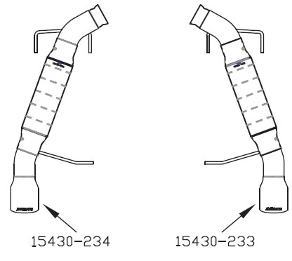
PACKING LIST
| Qty | Description | Part# |
|---|---|---|
| 1 | Muffler (R) | 15430-233 |
| 1 | Muffler (L) | 15430-234 |
| 1 | Parts Kit | PK574 |
| 2 | 3/8” Hanger Keepers | HW501 |
Removal:
1. Remove the two 15mm bolts that secure the upper panhard bar/brace to the body on the left side, just forward of the muffler. Pull the bar down to gain clearance for muffler removal.
2. Loosen the 13mm nuts on the clamped connections between the mufflers and the over-axle pipes. The bolts need to be backed out to the end of the threads in order to open the clamp enough to allow the flared ball connection of the inlet pipe to be removed.
3. There are three hangers on each muffler, two in the front and one in the rear. Separate the rear hanger rods from the rubber mount first, and slide the muffler forward and out of the front mounts. A silicone spray lubricant will help the hangers to slip out.
4. The factory clamps will be used to install the new mufflers however they are fastened to the original mufflers with a small tab and will need to be removed. This can be accomplished by wiggling the clamp back and forth to break the tab.
Installation:
1. Place the factory clamps removed in the previous step, onto the inlet pipes of the new mufflers. Slide the forward hanger rods into the rubber mounts, and then secure the rear hanger rod. Now the ball connection on the inlet pipe can be connected to the over–axle pipe. Level the muffler and tighten the clamp on the muffler enough to hold in position.
2. Push the upper panhard bar back up into position and re-attach with the original bolts.
3. Adjust the position of the mufflers to provide a satisfactory fit. A minimum of ½” clearance around all parts of the system must be maintained; while keeping suspension travel and vibration in mind. After adjustments have been made, securely tighten the clamps and place the push on retainers onto the rear hanger rods to prevent them from slipping out of the rubber mounts.
