 FREE 1 to 3-Day Delivery on Orders $149+ Details
How to Install a K&N FIPK Cold Air Intake on Your 1996-2004 Mustang GT
Installation Time
1 hours
Tools Required
- Flat blade screwdriver
- Pair of vise grips
- Pair of side cutters
- 8mm wrench
- 10mm wrench
- 5mm allen wrench
- Drill
- 11/16" drill bit

Shop Parts in this Guide
Installation
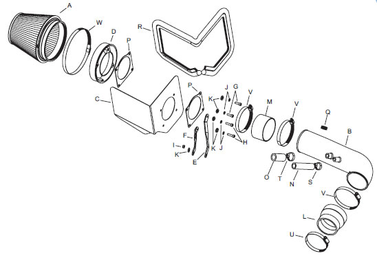
PARTS LIST:
| Description | Qty. | P/N | |
|---|---|---|---|
| A | Air filter | 1 | RF-1036 |
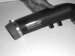
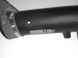
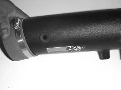
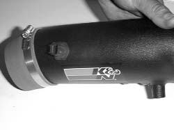
| B | Intake tube | 1 | 08738 |
| C | Heat shield | 1 | 07411 |
| D | Adapter | 1 | 08785 |
| E | Long twist bracket | 1 | 070762 |
| F | Short twist bracket | 1 | 070752 |
| G | 6mm-1.00 x 20mm allen bolt | 2 | 07852 |
| H | 6mm-1.00 x 25mm allen bolt | 2 | 07859 |
| I | Nylock nut | 1 | 07553 |
| J | Wave washer | 4 | 08174 |
| K | Flat washer | 5 | 08275 |
| L | Silicone step hose | 1 | 08724 |
| M | Silicone straight hose | 1 | 08630 |
| N | 5/8” ID vent hose | 1 | 08757 |
| O | 3/4” ID vent hose | 1 | 08709 |
| P | Gasket | 2 | 09984 |
| Q | Grommet | 1 | 08092 |
| R | Trim seal 44”L | 1 | 102486 |
| S | #10 hose clamp | 1 | 08411 |
| T | #12 hose clamp | 1 | 08420 |
| U | #48 hose clamp | 1 | 08601 |
| V | #56 hose clamp | 3 | 08620 |
| W | #104 hose clamp | 1 | 08697 |
NOTE: FAILURE TO FOLLOW INSTALLATION INSTRUCTIONS AND NOT USING THE PROVIDED HARDWARE MAY DAMAGE THE INTAKE TUBE, THROTTLE BODY AND ENGINE.
TO START:
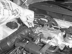
- Turn the ignition OFF and disconnect the vehicle's negative battery cable.
2. On models equipped with an external air temp sensor, disconnect the air temp sensor electrical connection.
3. Disconnect the mass air sensor electrical connection.
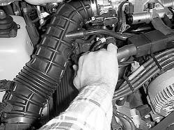
4. Loosen the hose clamp on the intake tube at the throttle body.
5. Loosen and remove the bolt that retains the air cleaner.
6. Detach the IAC line from the intake tube.
7. Detach the PCV line from the intake tube.
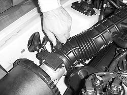
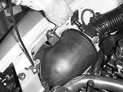
8. Remove the entire air intake assembly.
Note: K&N recommends that customers do not discard factory air intake.
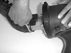
9. Loosen the hose clamp and detach the intake tube from the mass air sensor.
10. On models equipped with an external air temp sensor remove the air temperature sensor from the intake tube.
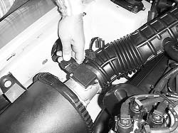
11. Loosen and remove the 4 nuts that retain the mass air sensor.
NOTE: It may be necessary to use a pair of vise grips to hold the studs while loosening the nuts.
12. Remove the mass air sensor from the air cleaner.
NOTE: The screen will not be reused.
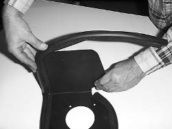
13. Install the trim seal onto the heat shield.
NOTE: some cutting and trimming will be necessary to achieve best fit.
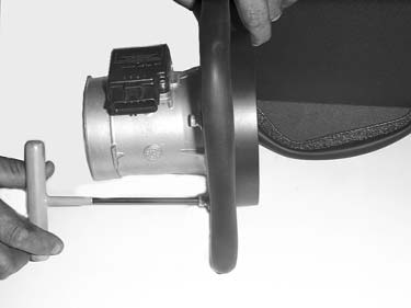
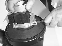
14. Assemble the mass air sensor, heat shield and adapter, using the gaskets and hardware provided as shown.
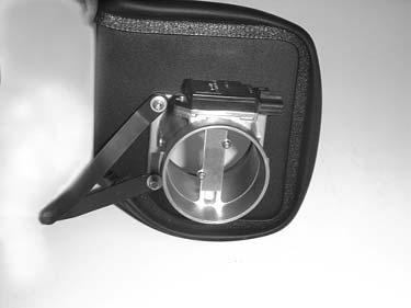
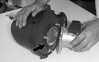
15. Attach the brackets to the mass air sensor as shown.
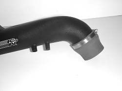
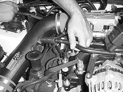
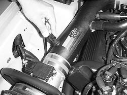
16. Attach the silicone step hose to the K&N intake tube using the hose clamp provided.
17. Attach the silicone straight hose (08630) to the K&N intake tube using the hose clamp provided.
18. On models equipped with an external air temp sensor, drill out the drill point using a 11/16” drill bit.
19. On models equipped with an external air temp sensor install the grommet into the hole in the previous step.
20. On models equipped with an external air temp sensor, drill out the drill point using a 11/16” drill bit.
21. On models equipped with an external air temp sensor, insert the air temperature sensor into the grommet.
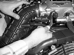
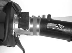
22. Attach the K&N intake tube to the flange on the mass air sensor using the hose clamp provided.
NOTE: Do not tighten completely at this time.
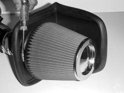
23. Attach the air filter element to the adapter using the hose clamp provided.
24. Loosen and remove the nut from the protruding stud on the engine.
NOTE: not all vehicles are equipped with a nut.
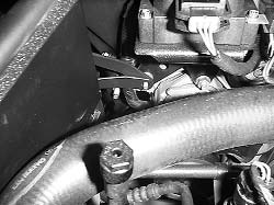
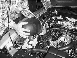
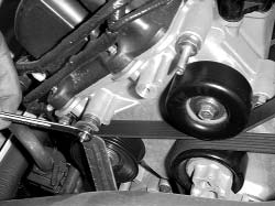
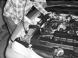
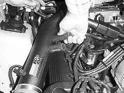
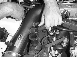
25. Install the K&N intake assembly, sliding the brackets onto the protruding stud on the engine as shown above.
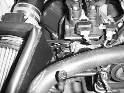
26. Secure the silicone step hose to the throttle body using the hose clamp provided.
27. Secure the brackets to the protruding stud using the hardware provided.
28. Attach the 5/8" and 3/4" ID vent hose provided onto the appropriate vent fittings on the intake tube using the hose clamps provided.
29. Install the PCV line into the 3/4” ID vent hose.
30. Install the IAC line into the 5/8” ID vent hose.
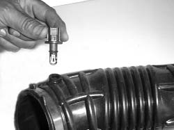
31. Reconnect the mass air sensor and air temperature sensor electrical connections.
NOTE: Not all models are equipped with an external air temp sensor.
32. Reconnect the vehicle’s negative battery cable. Double check to make sure everything is tight and properly positioned before starting the vehicle.
33. The C.A.R.B. exemption sticker, (attached), must be visible under the hood, so that an emissions inspector can see it when the vehicle is required to be tested for emissions. California requires testing every two years, other states may vary.
34. It will be necessary for all FIPK’s to be checked periodically for realignment, clearance and tightening of all connections. Failure to follow the above instructions or proper maintenance may void warranty.
Road Testing
1. Start the engine with the transmission in neutral or park, and the parking brake engaged. Listen for air leaks or odd noises. For air leaks secure hoses and connections. For odd noises, find cause and repair before proceeding. This kit will function identically to the factory system except for being louder and much more responsive.
2. Test drive the vehicle. Listen for odd noises or rattles and fix as necessary.
3. If road test is fine, you can now enjoy the added power and performance from your kit.
4. K&N suggests checking the air filter element periodically for excessive dirt build-up. When the element becomes covered in dirt (or once a year), service it according to the instructions on the Recharger service kit, part number 99-5050 or 99-5000

