 FREE 1 to 3-Day Delivery on Orders $149+ Details
How to Install Maximum Motorsports Competition Coil-Over Shock Mount Kit for MM Yellow Series Shock (79-04 All, Excluding 99-04 Cobra) on your Ford Mustang
Installation Time
2 hours
Tools Required
- Standard assortment of hand tools
- Torque wrench
- Floor jack
- Jack stands (2)

Shop Parts in this Guide
Read all instructions before beginning work. Following instructions in the proper sequence will ensure the best and easiest installation.
Required Supplemental Items
• Racing Upper Shock Mount (MMSM-1, -3, -5, -7, or -12)
• Driver Side Installation: Panhard Bar (MMPBA or MMPB99A) OR Lower Shock Mount Kit (MMSM-2)
• Passenger Side Installation: Lower Shock Mount Kit (MMSM-2)
• 2-1/4” Diameter Coil-over Spring
• Floor jack
• Jack stands (2)
Supplemental Installation Notes
• OEM lower shock mounts must NOT be used with coil-over shocks. They are not designed to take the added loads from a coil-over shock.
• Spring rates 225 lbs/in and softer will likely be preloaded for most ride heights. We recommend purchasing a MMT-2 Coil-Over Spanner Wrench to aid adjusting the spring preload.
• KYB and other brand of quad shocks with metal dust boots will not work with MM coil over kits. Bilstein and Koni quad shocks fit without modification. OEM quad shocks will need the plastic dust boot removed.
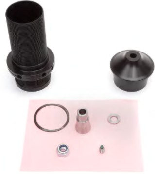
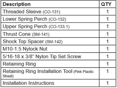
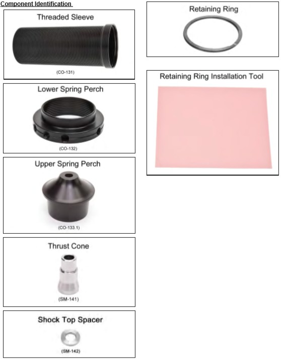
This Kit Contains
Vehicle Preparation
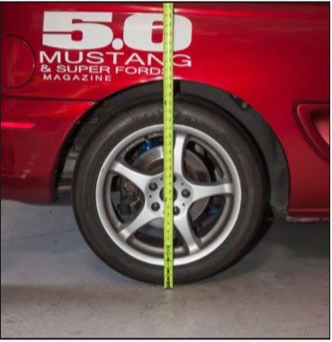
1. Measure and record the rear ride height of the vehicle, from the ground to the top of the fender opening.
2. Safely support the rear of the vehicle on jack stands placed under the frame rails.
3. Remove the rear wheels.
4. With a floor jack, support the side of the axle housing having the shock replaced.
5. Open the trunk and remove the shock top mounting nut and any mounting hardware from the shock being replaced. Depending on the vehicle, the trunk liner or plastic access panel must be removed to access the shock top.
6. Remove the shock eyelet mounting bolt.
7. Remove the shock from the vehicle. WARNING: Do not let the axle housing drop or damage to the brake hose will occur.
8. If installing a MMSM-2 Lower Shock Mount, do so at this step.
9. If a MM Racing Upper Shock Mount has not previously been installed on the vehicle, follow the MMSM-12 installation instructions now. One MMSM-12 Racing Upper Shock Mount is needed per shock.
NOTE: The MMCO-21 Coil-over Kit will work with previously installed MM Racing Upper Shock Mount kits MMSM-1, MMSM-3, MMSM-5, and MMSM-7. Remove any inserts/reducers that may be present in the spherical bearing of the upper shock mount and contine on to the next step.
Threaded Sleeve Installation
10. If upgrading a previously installed MMDRC0xxxx shock to a coil-over shock, discard everything from the shock shaft except the bumpstop.
11. Slide the threaded sleeve over the lower shock eyelet and onto the shock body. The nonthreaded sleeve section is positioned closest to the lower eyelet.
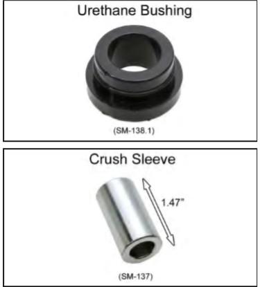
NOTE: If urethane bushings have previously been installed in the lower shock eyelet, they must be removed in order to install the threaded sleeve and retaining ring. Push out the crush sleeve and use a pair of pliers to pull out the bushings.
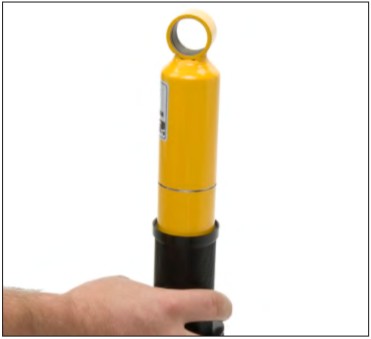
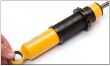
12. Install the provided retaining ring into the groove machined in shock body. The provided installation tool will expand the retaining ring over the shock body to aid installation. Use the following technique:
• Hold the shock upside down.
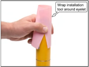
• Wrap the installation tool around the shock body with half of the tool extending over the shock eyelet in a slight conical shape (like a Native American Teepee).
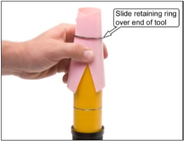
• Place the retaining ring over the tip of the tool.
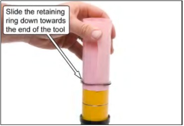
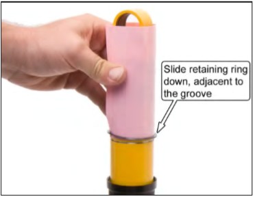
• Slide the retaining ring down to the opposite end of the tool. You will need to push down pretty hard.
• Slide the installation tool, with the retaining ring still on the end of it, down to the machined groove in the shock body.
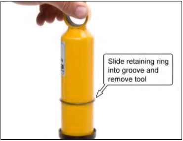
• Slide the retaining ring off the tool and into the groove.
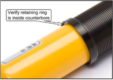
13. Slide the threaded sleeve over the retaining ring so that the counterbore completely encapsulates the retaining ring.
14. Thread the lower spring perch to the base of the threaded sleeve.
15. Thread the provided Nylon tipped set screw a few turns into the threaded hole on the lower spring perch.
16. Shocks with spherical bearing lower eyelets, proceed to Step 21.
Shock Eyelet Preparation
NOTE: The components in this section are included with the MMD-RC0xxxx-U shock.
17. Apply a small amount of provided grease to the inside of the shock’s lower eyelet and the outside diameter of the two urethane bushings.
18. Install the two urethane bushings into the eyelet.
19. Apply a small amount of grease to the inside of the urethane bushings.
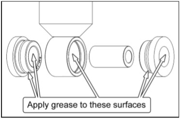
20. Insert the crush sleeve into the urethane bushings. Use a vise or large set of pliers to press in the crush sleeve. A rubber mallet can also be used to tap in the crush sleeve.
Coil-over Upper Perch Installation
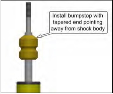
21. Install the provided bumpstop with the tapered end pointing away from the shock body.
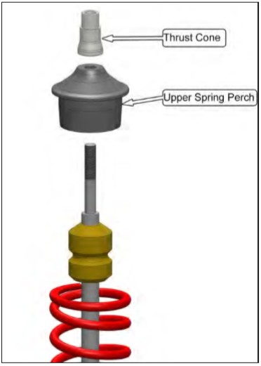
22. Install a 2-1/4” diameter coil spring over the threaded sleeve and onto the lower spring perch.
23. Install the upper spring perch onto the shock shaft.
24. Install the Thrust Cone onto the shock shaft.
Shock Installation
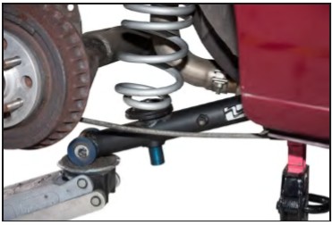
25. Install the top of the shock assembly into the shock tower. The reduced section of the Thrust Cone must slide into the spherical bearing of the Racing Upper Shock Mount.
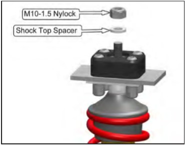
26. Identify the remaining components from the MMCO-21 Coil-over Kit and install them in the order shown below. Hand tighten the Nylock nut for now.
I. Shock Top Spacer
II. M10-1.5 Nylock Nut
27. Install the shock eyelet mounting bolt and nut. It will be necessary to raise the floor jack to align the mounting holes to the shock eyelet, as the MM shocks have reduced droop travel.
NOTE: Install the bolt from the inboard side of the shock.
28. Torque the shock eyelet mounting nut to 59 lb-ft.
Stock Location Spring Removal
29. If a stock style rear swaybar is installed, disconnect it from the control arms, along with the parking brake cable bracket if present.
30. Support a rear lower control arm as close to the rear axle as possible with a floor jack.
31. Remove the rear control arm axle pivot bolt and gradually relieve the spring tension by slowly lowering the jack until the spring is completely uncompressed.
32. Remove the spring and spring isolators.
33. With the spring removed, raise the control arm back into place and reinsert the pivot bolt and nut.
34. If using urethane or spherical bushed control arms, torque the pivot bolt now. If using OEM rubber bushed control arms, raise the floor jack until the control arm is roughly parallel with the frame rail before torquing the bolt.
1979-98 Mustangs: 86 lb-ft
1999-04 Mustangs: 111 lb-ft
35. On 1979-93 vehicles, a factory bumpstop is installed on the frame rail directly above the axle housing. Use a large pair of pliers to remove the bumpstop from its mounting bracket.
36. As an initial starting point, raise the lower spring perch until the upper spring perch just enters the opening in the top of the spring.
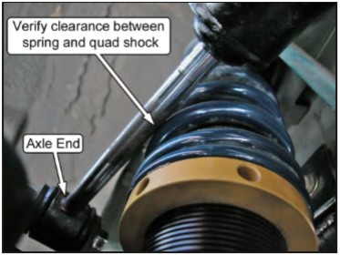
37. If the vehicle is equipped with quad shocks, verify that there is sufficient clearance between the outside of the coil-over spring and the quad shock piston rod. If needed, unbolt the rearward end of the quad shock from the frame-mounted stud and install a few 12mm washers onto the stud, to space the quad shock further outboard.
NOTE: The dust boot on Ford quad shocks will need to be removed. KYB and other brands of quad shocks with metal dust boots will not work with MM coil-over kits without modification.
38. Once the driver and passenger side coilover kits have been installed, reinstall the rear swaybar and parking brake cable bracket if it was removed. If you have an aftermarket swaybar, consult the manufacturer’s instructions for bolt torque. Torque the OEM swaybar mounting bolts to 41 lb-ft.
39. Reinstall the wheels.
40. Safely lower the vehicle to the ground.
41. Torque the lugs nuts to the manufacturer’s specifications.
42. Torque the M10-1.5 Nylock nut on each shock shaft to 16 lb-ft.
Setting Ride Height
43. Roll the car back and forth to settle the suspension.
44. Measure the ride height as done in Step 1. Compare to the dimension recorded in Step 1, and determine if the car needs to be raised or lowered to match that starting ride height. If a different ride height is desired, we suggest first adjusting to match the previous ride height, and then making further adjustments.
NOTE: Be sure to adjust both perches to the same height to avoid upsetting the corner weight balance. Measure the distance from the base of each threaded sleeve to the bottom of each perch and verify that the distances match.
45. Support the car on jack stands to get the weight off the springs, and adjust the spring perches.
46. Hold the threaded sleeve with one hand and turn the lower spring perch with your other hand. (up, to raise the car, and down, to lower the car)
NOTE: If you need to preload the spring, use MM’s spanner wrench to help rotate the lower spring perch
47. Lower the car and repeat steps 43-46 until the desired ride height is achieved.
48. Once the ride height is correct, use a 5/32” hex key to snug the nylon tipped set screw in the lower spring perch. This will hold the spring perch in position.
WARNING: Do NOT overtighten the setscrew. It only needs to be tight enough to prevent the spring perch from rotating. Overtightening it can damage the perch, the threaded sleeve, and even the shock.
49. Test drive.
