 FREE 1 to 3-Day Delivery on Orders $149+ Details
How to Install Maximum Motorsports IRS Bumpsteer Kit on your Mustang

Shop Parts in this Guide
Read all instructions before beginning work. Following instructions in the proper sequence will ensure the best and easiest installation.
Just as with the front of a vehicle, making changes to enhance the performance of an independent rear suspension system will often require tuning the alignment. Besides the commonly required adjustments to camber and toe, an IRS can greatly benefit from fine-tuning its bumpsteer characteristics. The MM Adjustable Independent Rear Suspension (IRS) Tie-Rod End Kit is designed to allow adjustment of the rear steering geometry in order to minimize the amount of bumpsteer.
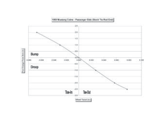
Bumpsteer is the term for the situation when the toe angle of a wheel changes as the suspension moves up and down, such as when driving over bumps, or with body roll during cornering. This happens when the arc that the spindle travels during bump and droop is not the same as the arc of the outer tie-rod end. If the toe changes more than a very small amount, the rear wheels begin steering the car. Bumpsteer is commonly measured and then plotted on an X-Y coordinate graph as a curve showing suspension travel vs. toe change. The resulting curve is an illustration of the bumpsteer characteristics. We have found significant variations in the bumpsteer curves measured on different IRS equipped Mustangs. Differences in the bumpsteer characteristics exist not just from one vehicle to another, but also on the same car, from one side to the other side. As the level of desired performance is raised, and the number of modifications to the suspension climbs, the importance of adjusting the bumpsteer on each side of your car becomes increasingly important.
Ford designed the rear suspension to function as a complete system. The static bumpsteer curve was designed to work in conjunction with the compliance of all the rubber bushings in the suspension. When those bushings are changed to a less compliant material, the dynamic bumpsteer curve will change and no longer be what Ford had intended.
Only the static bumpsteer curve can be measured, because it is impossible to measure changes in toe while the car is being driven. We can only assume that the static bumpsteer curve we measure provides the dynamic curve, and therefore the handling balance of the car, that Ford intended. With the installation of urethane or Delrin suspension bushings there will be far less compliance in the bushings, and therefore the alignment changes when the car is driven will be smaller in magnitude. The original static bumpsteer curve will no longer allow the same dynamic curve that the car had with the original rubber bushings. This will affect the handling balance of the car, which is why MM recommends measuring and adjusting the rear bumpsteer on your car as part of your performance modifications.
The vertical mounting position of the IRS inner tie-rod end on the 2003 Cobra was altered from its location in the previous years. The new position altered the bumpsteer curve. While this reduced the understeer of stock 2003-04 Cobras, there can still be problems once the vehicle’s suspension is modified. For earlier IRS Cobras, the simple fix of duplicating the 2003 Cobra bumpsteer curve becomes less and less desirable as the compliance of the OEM suspension is reduced. MM recommends matching the 2003 Cobra static bumpsteer curve only for cars that retain the original factory rubber bushings.
For cars with any performance upgrades, such as springs, IRS subframe bushings, or rear control arm bushings, MM recommends that the rear bumpsteer curve be adjusted to minimize any toe changes with suspension movement. After you test your car with this set-up, you may fine-tune the handling balance of the car by adjusting the rear bumpsteer curve. Only your continued testing will confirm what works best for your car and your driving style.
NOTE: You will need to have the rear toe setting professionally adjusted after installing this part.
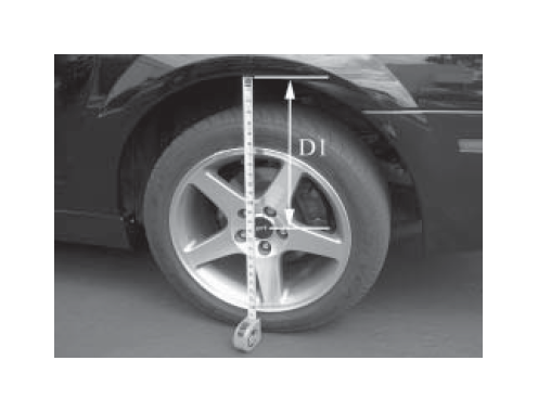
1. If you will be adjusting the bumpsteer, before jacking up the car measure the distance between the rear wheel’s hub center and the fender lip. This is your baseline ride height. Record this dimension for later use.
2. Jack up the rear of the car and place it safely on two jackstands. Position the jackstands under the chassis, not under the control arms.
3. Remove the rear wheels.
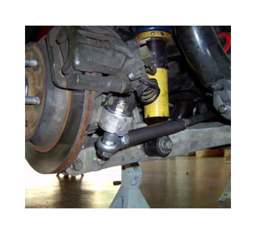
4. Support the control arm just above full droop with a jackstand. Starting on the driver’s side of the car, loosen and remove the lower shock mounting bolt. This creates room to move the tie-rod more freely.
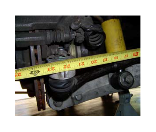
5. Make a vertical reference mark on the rear face of the steering arm. Take a reference measurement between the reference mark and a point on the tie-rod near it’s inner end, such as the outboard side of the inner jam nut.. Record this dimension, as it will be used later to adjust the length of the tie-rod.
6. Loosen the jam nut securing the outer tie-rod end. Thread it onto the tie rod as far as possible. The outer tie-rod jam nut is a right-hand thread.
7. Loosen the jam nut securing the inner tie-rod end. Thread it onto the tie-rod as far possible. The inner tie rod jam nut is a left-hand thread.
8. Remove the nut securing the tie-rod end to the spindle. Apply penetrating oil to the tie-rod end where it comes through the spindle.
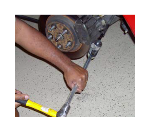
9. Using a suitable tie-rod end splitting tool, separate the outer tie rod end from the steering arm of the spindle. To avoid damage to the control arm, the tie-rod end splitting tool should be held at an orientation generally parallel to the axle centerline of the IRS.
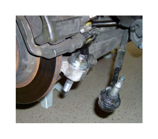
10. Install one of the supplied tapered studs through the steering arm of the spindle. Secure the tapered stud to the steering arm using one of the supplied washers and 1/2-13 lock nuts. Torque the lock nut to 50 ft-lbs.
Note: If the tapered stud spins while tightening the lock nut, thread the two supplied standard (non-locking) 5/8-18 nuts onto the lower portion of the stud and tighten them against one another. Hold the lower of these two jammed nuts while tightening the top lock nut and securing the tapered stud. Remove the two nuts after torquing the top locking nut.
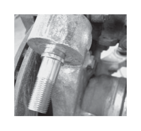
Note: The shoulder of the tapered stud will not contact the bottom surface of the steering arm. The shoulder is designed to provide a stop for the spacers in your MM Kit. The tightly controlled taper dimensions (both on the Ford steering arm, and on the MM Tapered Stud) control how deep the stud sets into the tapered hole.
11. Unthread and remove the outer tie-rod end from the tie-rod.
12. Thread the tie-rod into the inner tie-rod end until it bottoms out.
13. Thread the aluminum sleeve of the MM Outer Tie-Rod End onto the tie-rod as far as it will go. Use anti-seize compound on the threads.
14. Slip the .060” thick spacer onto the bottom of the tapered stud. This spacer will make the bumpsteer curve approximately the same as the 2003 Cobra. In the absence of measuring the bumpsteer on your car, MM recommends this bumpsteer geometry for cars retaining the rubber bushings in the rear suspension.
Note: To properly adjust the car’s bumpsteer curve will require use of an MM Bumpsteer Gauge. Use of this gauge will allow you to adjust the spacer stacks on your tie-rod ends to minimize bumpsteer effects. For cars that have had the factory rubber bushings replaced with urethane or Delrin, we highly recommend tuning the bumpsteer curve in this manner for best handling.
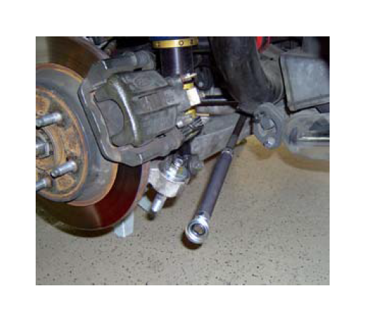
15. Slip the tie-rod end onto the stud.
16. Slip the thickest of the remaining spacers onto the the stud below the tie-rod end. This acts as a washer for the lock nut.
17. Thread the 5/8-18 locking nut onto the stud and torque to 65 ft-lbs..
18. Reinstall the lower shock mounting bolt. Torque to 98 ft-lbs.
19. Remove jackstand supporting the control arm, and allow the arm to sit at full droop.
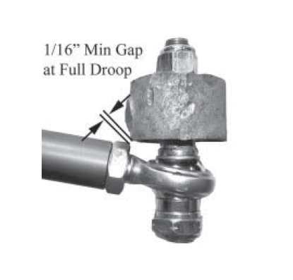
20. Check the clearance between the jam nut on the spherical rod end and the arm on the spindle. Make sure there is at least 1/16" clearance when the suspension is at full droop. If there is not, loosen the jam nut and unthread the spherical rod end out of the aluminum sleeve to provide the clearance. The spherical rod end should not need to be unthreaded more than one or two turns. Re-tighten the jam nut.
21. The length of the tie-rod assembly is adjusted by rotating the tie-rod. Lengthen the assembly to match the dimension recorded in Step 4.
22. Place the jack under the outermost portion of the control arm. Jack the control arm to ride height (as measured in Step 1.) If the car comes up off the jackstand before reaching ride height, stop there.
23. Tighten the tie-rod’s outer jam nut to 41 ft-lbs..
24. With the inner jam nut loose, grab the aluminum outer tie-rod sleeve and rotate it by hand. The tie-rod end should be rotating on the spherical bearing. Find the full range of twisting motion, and rotate the sleeve so that the tie-rod end is in the middle of the range. This will properly clock the tie-rod end so that it will not bind over the full range of suspension travel.
25. Tighten the tie-rod inner jam nut to 41 ft-lbs..
26. Repeat steps 3 to 25 on the other side of the car.
27. If you will be measuring and adjusting the bumpsteer, jack up the front of the car and place it safely on two jackstands so that the car is approximately level.
28. Disconnect the swaybar end links from the control arms.
29. The spring must be inactive on the side that you will be measuring bumpsteer. • If you have rear coil-overs, lower the rear lower spring perch. Be sure to count the number of turns so you can restore the ride height afterwards.
• If you car has a conventional spring, the spring can be compressed onto the control arm, but does not need to be removed.
• To do this, use an internal spring compressor hooked to the spring near its top, and hooked to the lower control arm through its center hole. Compress the spring down onto the control arm.
• Place a jack directly underneath the lower control arm’s outer pivot, at the spindle.
• Jack the control arm up until the hub center is the same distance below the fender lip that you recorded in step 1. This is your baseline ride height to start measuring bumpsteer.
• Refer to the instructions that came with your MM Bumpsteer Gauge to measure the bumpsteer curve. To maintain consistency in measuring the toe changes, always place the bumpsteer gauge’s dial indicator towards the rear of the car, and measure the vertical travel at the dial indicator.
• Depending on ride height, the Cobra IRS has approximately 2" of travel in both bump and droop.
• Measure and adjust the bumpsteer on both sides of the car. Do not be surprised if the spacer stacks on each side of the car that provide the same bumpsteer curves are different.
30. Reconnect the swaybar end links and torque to 35 ftlbs.
31. Reinstall the rear wheels. Torque the lug nuts to factory or wheel manufacturer’s specs.
32. Lower the car safely to the ground, and have the rear toe setting professionally aligned.
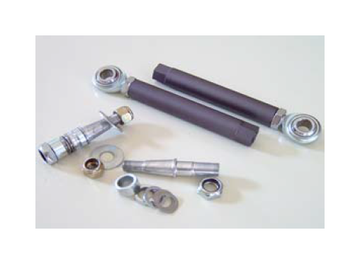
This kit includes:
2 Tie Rod Aluminum Sleeves
2 5/8” Rod Ends (Assembled to Sleeves)
2 5/8” Jam Nuts (Assembled to Sleeves)
2 5/8”-18 G5 Nuts (for use in installation)
2 Tapered Bumpsteer Studs
2 1/2” -20 G8 Nylock Nuts
2 5/8”-18 G8 Nylock Nuts
2 1/2” G8 Flat Washers
2 Bumpsteer Spacer - .24” thick
2 Bumpsteer Spacer - .12” thick
2 Bumpsteer Spacer - .06” thick
2 Bumpsteer Spacer - .03” thick
2 Bumpsteer Spacer - .015” thick
