FREE 1 to 3-Day Delivery on Orders $149+ Details
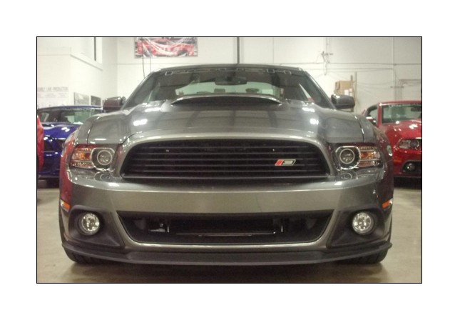
How to Install Roush High-Flow Lower Grille Delete (13-14 GT, V6) on your Mustang
Tools Required
- Ratchet (1)
- 7 mm Metric Socket (1)
- Deburring Tool (1)
- Air Saw (1)
- Soap and Water
- Drill (1)
- Drill Bit Set (1)
- Small Plastic Squeegee
- Safety Glasses
- 8 mm Metric Socket (1)
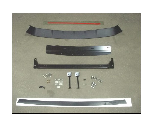
Before installing your ROUSH Performance Product(s), read through the entire installation procedure and check to make sure all items are present. Contact ROUSH Customer Service at 1-800-59-ROUSH, weekdays from 9:00 AM to 5:00 PM EST, with any questions regarding fit, missing parts or instructions that are unclear to you.
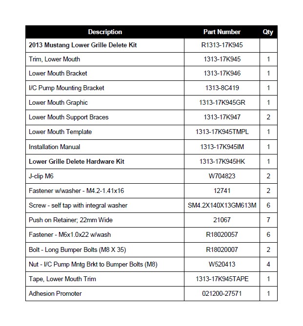
Packaging List for 2013 Mustang Lower Grille Delete Kit
LIMIT OF LIABILITY STATEMENT
The information contained in this publication was accurate and in effect at the time the
publication was approved for printing and is subject to change without notice or liability.
ROUSH Performance Products (RPP) reserves the right to revise the information
presented herein or to discontinue the production of parts described at any time.
SAFETY REQUIREMENTS
STOP! READ IMPORTANT SAFETY CAUTIONS AND WARNINGS BEFORE
PROCEEDING.
IMPORTANT SAFETY NOTICE
Appropriate disassembly, assembly methods and procedures are essential to ensure
the personal safety of the individual performing the kit installation. Improper installation
due to the failure to correctly follow these instructions could cause personal injury or
death. Read each step of the installation manual carefully before starting the actual
installation.
Always wear safety glasses for eye protection.
Place ignition switch in the OFF position.
Always apply the parking brake when working on a vehicle.
Chock the front and rear tires to prevent unexpected vehicle movement.
If working without a lift, always consult vehicle manual for correct lifting specifications.
Operate the engine only in well-ventilated areas to avoid exposure to carbon monoxide.
Do not smoke or use flammable items near or around the fuel system.
Use chemicals and cleaners in well-ventilated areas.
Batteries produce explosive gases, which can cause personal injury. Therefore, do not
allow flames, sparks or flammable substances to come near the battery.
Keep hands and any other objects away from the radiator fan blades.
Keep yourself and your clothing away from moving parts when the engine is running.
Do not wear loose clothing or jewelry that can get caught in rotating parts or scratch
surface finishes.
Allow the engine, cooling system, brakes and exhaust to cool before working on a vehicle.
WORK SAFELY!
Perform this installation on a good clean level surface for maximum safety and with the
engine turned off.
SECTION A – Removal
The following section will guide you through the removal of the factory upper grille.
1. With the vehicle in NEUTRAL, position it on a hoist, raise and properly support.
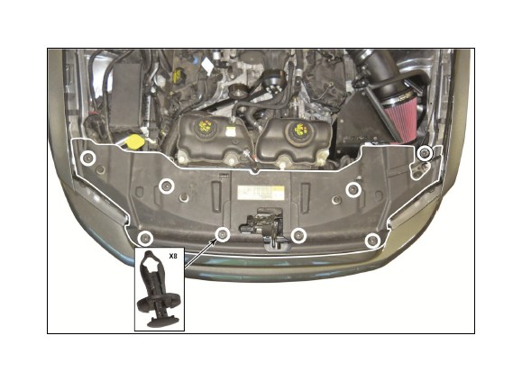
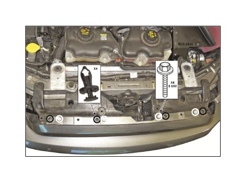
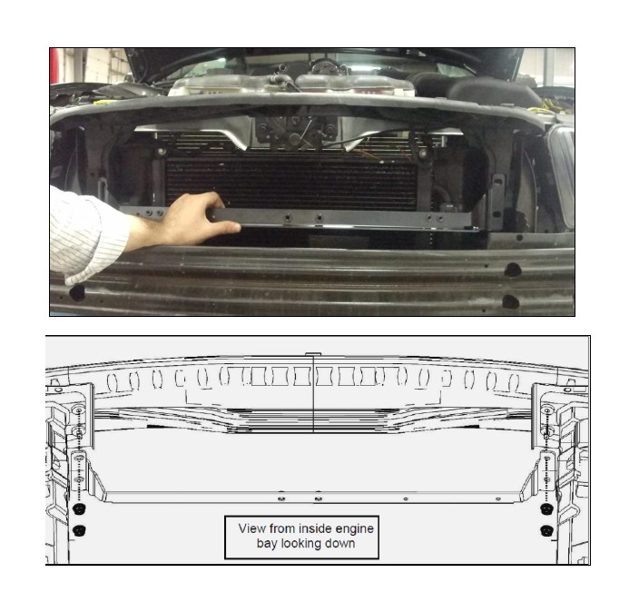
2. Open the hood and remove the eight (8) pin-type retainers and the upper radiator
closeout panel.
3. Remove the four (4) pin-type retainers and the four (4) 8 mm bolts from the top of
the bumper cover.
● To install, tighten bolts to 3 Nm (27 lb-in).
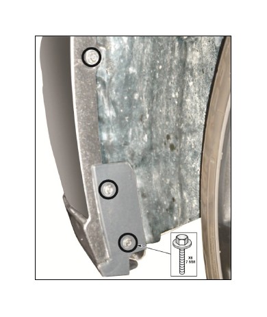
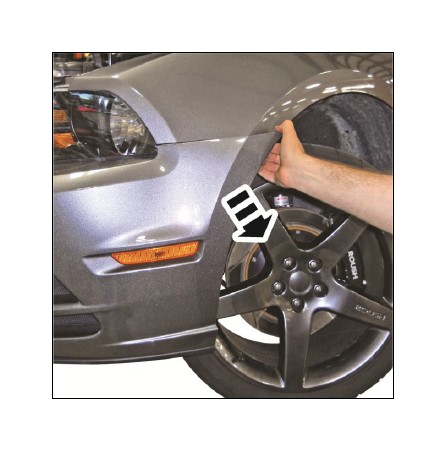
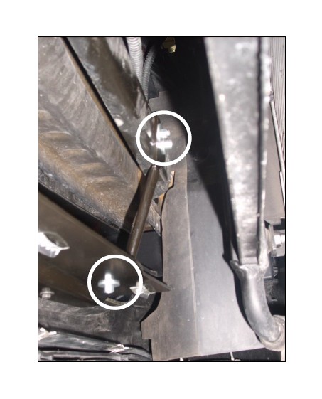
4. Turn the wheel to the right to gain access to the three (3) 7 mm bolts on the LH
side of the vehicle and repeat on the RH side of the vehicle.
● To install, tighten bolts to 1.3 Nm (12 lb-in).
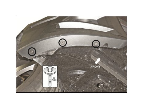
5. Remove the three (3) 7 mm outer lower valance bolts on the RH side. Repeat on
the LH side.
● To install, tighten bolts to 3.2 Nm (28 lb-in).
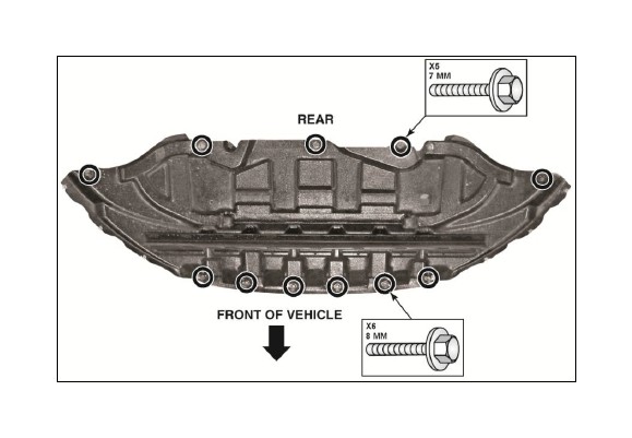
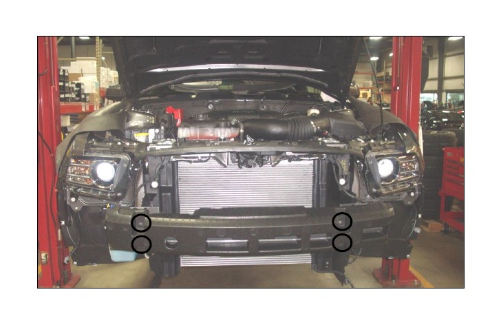
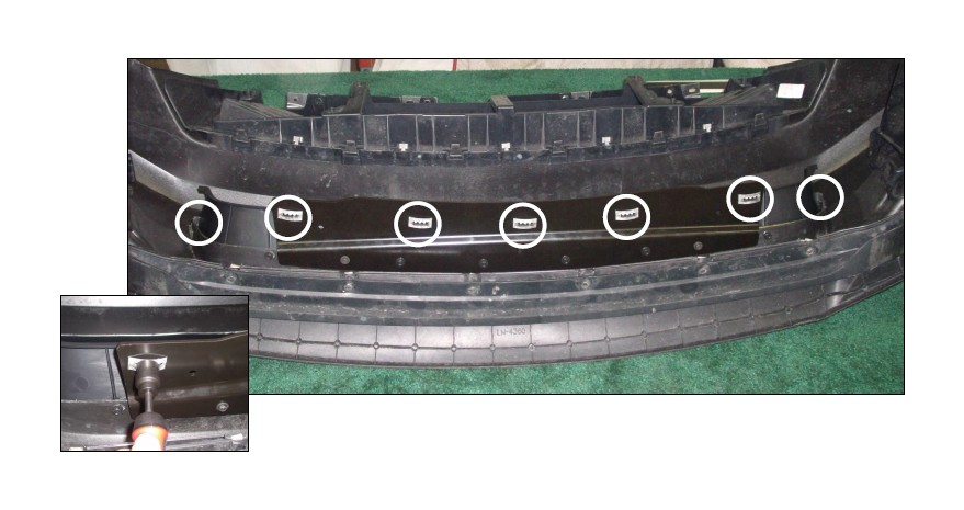
6. Remove the front six (6) 8 mm bolts, the rear five (5) 7 mm bolts and pull down and
back to remove the lower air deflector.
● To install, tighten bolts to 3.2 Nm (28 lb-in).
7. Disconnect the two (2) side marker light connectors on the LH and RH side.
CAUTION: To protect the bottom of the bumper cover from damage, place on a
protective surface once removed.
8. Pull outward to unsnap the LH and RH sides of the bumper cover.
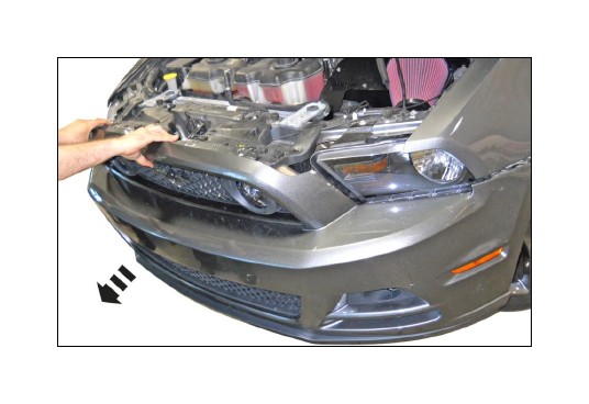
NOTE: If equipped, disconnect the fog lamp connectors.
SECTION B – Modification
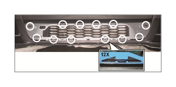
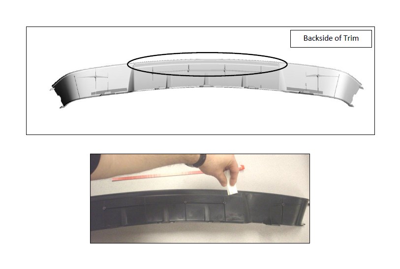
9. Position the front bumper surface on an appropriate work surface to prevent
damage while modifying the lower grille opening. Remove the factory lower grille
insert. Using a suitable trim tool, release the twelve (12) retaining tabs.
Note: Back side of bumper cover shown.
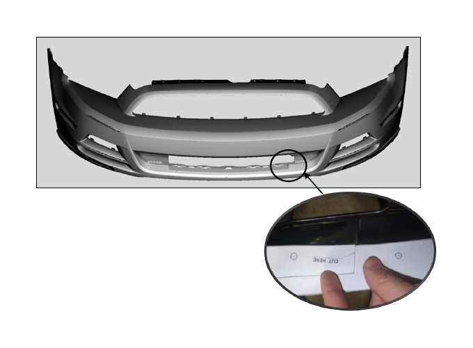
10. Cut out the lower mouth template (1313-17K945TMPL). Using the cut features on
the template to assist in locating, position the lower mouth template into the front
side of the fascia. Center the template into the lower mouth (right side shown,
match left side evenly with the right).
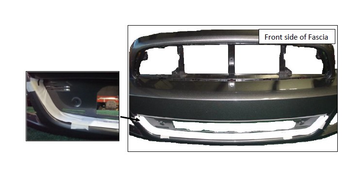
11. Position the lower mouth template against the grille mounting surface as shown.
Tape the template in multiple places to keep it from moving while working.
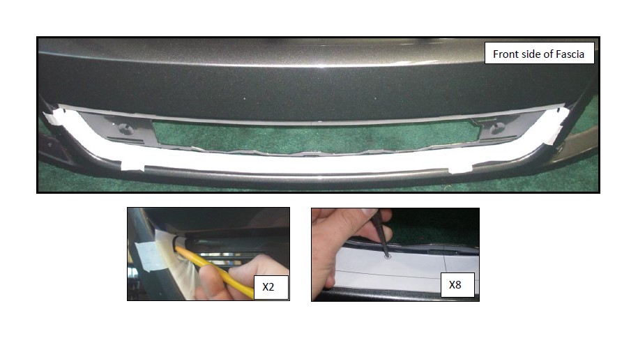
12. Using a china marker or other marking device, mark the two slots cutout at the
ends of the templates. Using an automatic center punch, mark the locations of the
eight (8) holes on the lower mouth template.
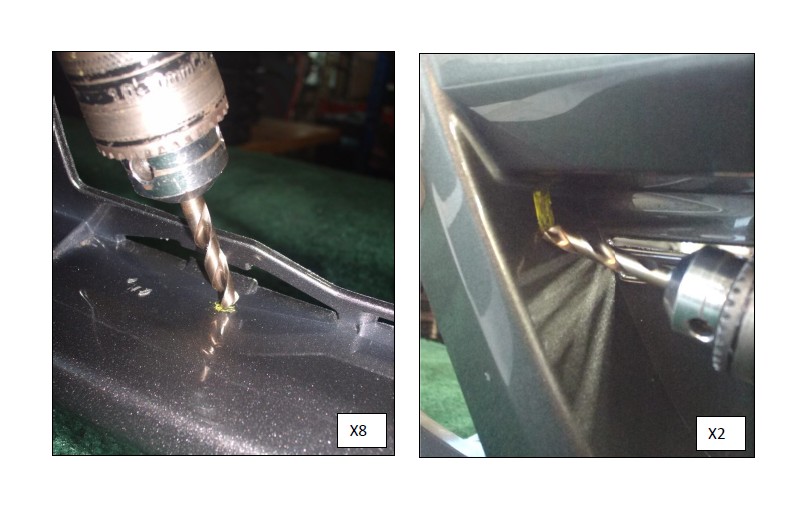
13. With a 90 degree angle drill and a short 1/8” drill bit, pilot drill the eight (8) hole
locations and the two (2) slot locations marked in the previous step. Using a ¼” drill
bit open the eight (8) holes and two (2) slot locations. Using caution, elongate the
two (2) slots. Note: Use caution when drilling; do not contact the painted
surfaces with the rotating drill chuck.
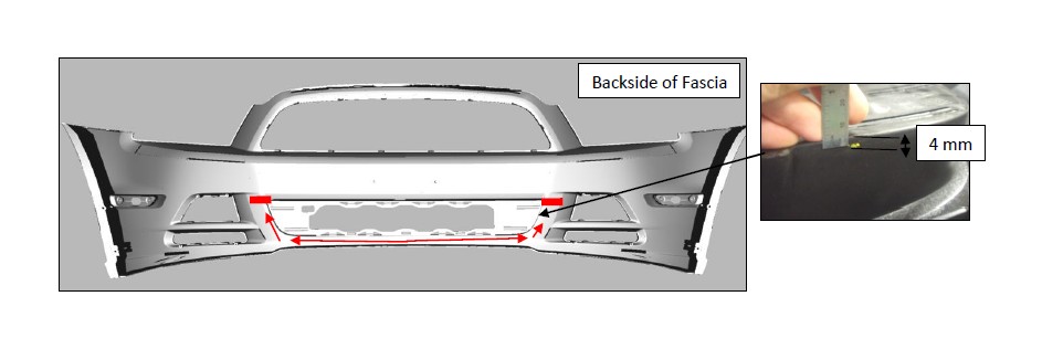
14. On the backside-lower surface of the grille mounting recess, with an appropriate
measuring device, measure 4 mm down from the surface. Mark the fascia at this
measurement in several locations. Continue measuring and marking around the
arc of the lower grille shape to the top left and right corners.
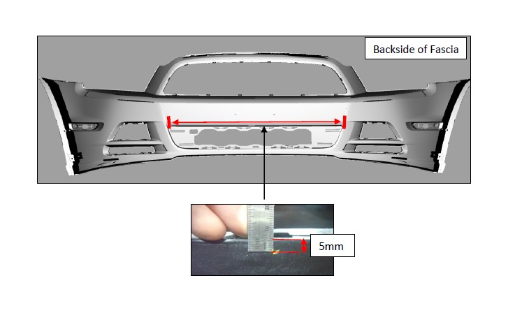
15. On the top side of the lower grille mounting surface, measure down 5 mm and mark
in several locations along the perimeter of the recessed area.
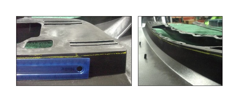
16. With a straight edge, connect the lines marked in the previous steps around the
entire perimeter of the grille mounting recess. Using an air saw or other suitable
cutting tool, use the line as a guide in removing the backside of the grille recess.
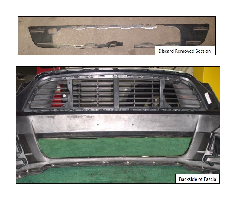
17. Once the backside of the grille recess is removed, the cut section should be similar
to what is illustrated below.
SECTION C – Installation
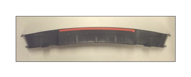
1. Apply the included Adhesion Promoter (021200-27571) to the area where the
tape (1313-17K945TAPE) is to be applied to the lower mouth trim insert (1313-
17K945).
2. Install the tape (1313-17K945TAPE) onto the lower mouth trim piece as shown
in the image below.
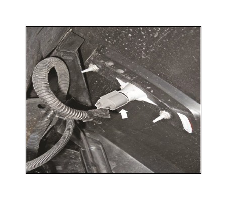
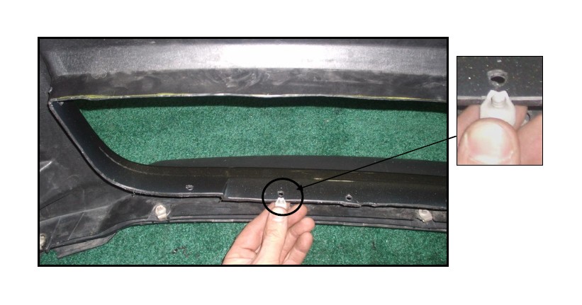
3. Using a suitable trim tool, remove the four (4) plastic push pins from the foam
bumper isolator to access the four (4) inner bumper reinforcement bolts.
4. With a 13mm socket remove the inner four (4) front bumper reinforcement bolts.
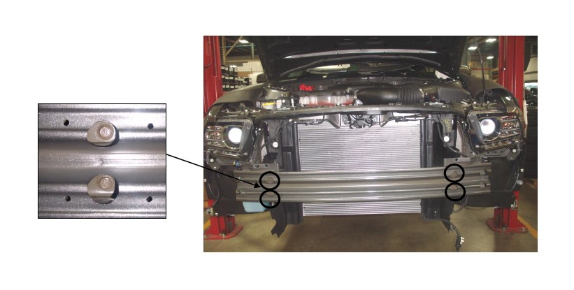
5. Install the four (4) bolts (R18020007) in place of the four (4) which were
removed in the prior step and torque to 25 Nm. Install the Intercooler Pump
Mounting Bracket (13108C419) behind the bumper onto the long bumper bolts
using (4) M8 nuts (W520413). Torque to 25 Nm.
6. Install the two (2) J-clips (W704823) in the left and right 2nd to outside holes
drilled in step 13 of section B. Orient the J-clips so the threaded portion is
upward. (Driver side shown, repeat on passenger side).
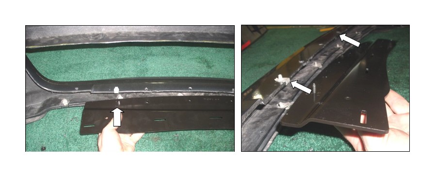
7. Loosely install the support bracket (1313-17K946) with two (2) screws (12741)
into the location of the J-clips installed in the previous step. Inspect the four (4)
free additional holes in the bracket to verify the holes drilled through the fascia in
step 13, section B are aligned properly.
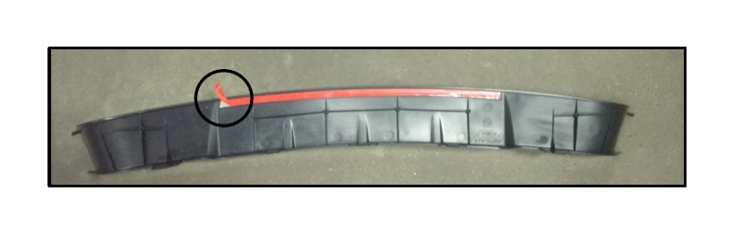
8. Bend the free length of the red tape film on the lower mouth trim piece (1313-
17K945) over toward the outside edge of the part so that it is free to pull off
once the trim piece is installed.
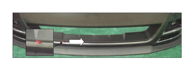
9. Loosely place the lower mouth trim piece into the lower grille opening. Line up
the tabs in the left and right corners with the slots of the fascia. Be sure the tape
film is accessible for removal.
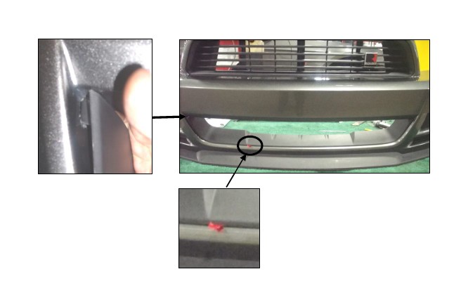
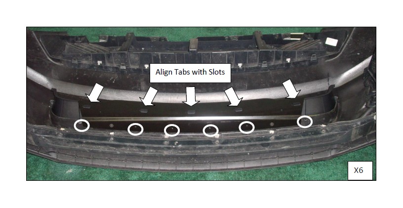
10. Turn the fascia front side down. Align the remaining five (5) tabs with the lower
mouth reinforcement bracket slots. Loosely install the six (6) screws
(SM4.2X140X13GM613M) in the remaining four (4) holes of the reinforcement
bracket and the two (2) outermost holes.
11. Orient the fascia so the lower mouth opening is accessible. Check the right
and left corners to be sure the tabs of the lower mouth trim are still aligned with
the fascia. Remove the red tape film by slowly peeling it away from the fascia.
Once the film is completely removed, press firmly along the surface where the
tape was applied.
12. Access the backside of the fascia. Tighten the six (6) screws installed in step
10 to 1 Nm. Tighten the two (2) screws installed in step 7 to 3 Nm.
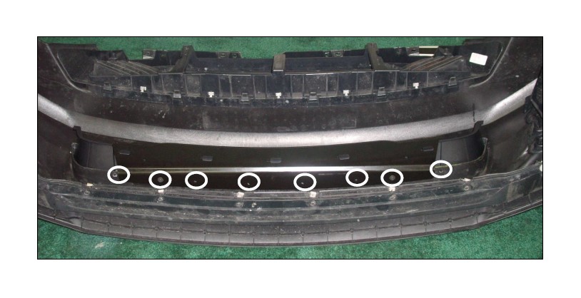
13. Install the seven (7) retaining clips (21067) onto the seven (7) lower mouth trim
tabs, centering the tab within the clip and pressing firmly. Note: a drum brake
spring tool is recommended for pressing the clips onto the tabs.
14. Loosely mount the front fascia onto the vehicle. Using four (4) bolts
(R18020057), install the two (2) pencil braces (1313-17K947) onto the
intercooler pump mounting bracket installed in step 5. Using the remaining two
(2) bolts (R18020057), install the pencil bracket to the lower mouth support
bracket. Torque the six (6) bolts to 10 Nm.
15. Reverse the procedure in section A to install the front fascia.
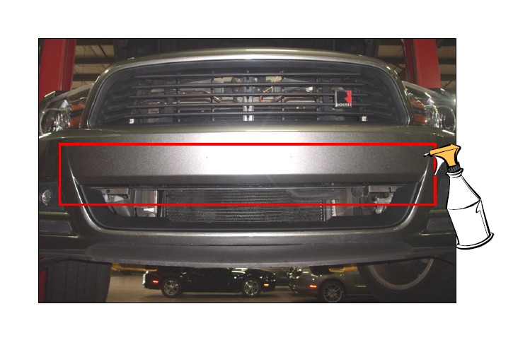
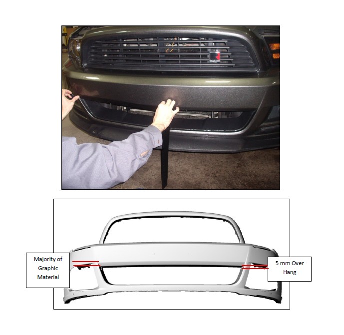
SECTION D: Graphic Installation
1. With the front fascia installed, apply soapy water to the surface of the fascia just
above the lower mouth.
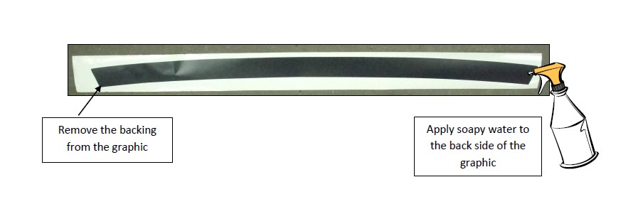
2. Remove the white backing from the black graphic (1313-17K945GR) and apply
soapy water to the backside of the graphic to aid in installation.
3. Install the graphic just above the lower mouth opening. Allow 5 mm of the
graphic to hang just beyond the last body line leading into the lower mouth
opening.
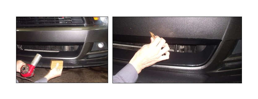
4. After the graphic is aligned and flat, run a plastic squeegee along the surface of
the graphic to remove the soapy water and air bubbles. If any ripples form in
the material, apply heat using a heat gun to remove the ripples.
Congratulations!!! You have completed the installation of your new ROUSH Performance
Products Mustang Lower Grille Delete Kit.