FREE 1 to 3-Day Delivery on Orders $149+ Details
How to Install Stainless Works Off-Road H-Pipe on your Mustang
Thanks for purchasing Stainless Works Muscleflow Headers for your 07-10 Shelby Cobra GT500. We have gone to great pains to make sure that our exhaust systems fit and sound great. Please follow these steps to ensure that your installation goes as planned.
1. Stainless Works recommends the use of Hi-Temp RTV sensor safe silicon gasket
maker as an option to or in conjunction with the use of factory gaskets. The
recommended Oxygen Sensor Safe RTV is either Valco All-in-One Aluminum or
Permatex Copper P/N 101BR, available at NAPA, Autozone and other retailers.
2. Disconnect the battery before starting work on the exhaust system for your
vehicle. Reconnect the battery when the job is completed.
3. Your exhaust system can be installed by a weekend warrior but the use of a lift is
recommended for ease of installation. If using a jack, the vehicle must be placed
on a level hard surface and jack stands are required for safety reasons Raise the
vehicle as high as possible for easy removal of the manifolds..
4. Disconnect battery, remove strut tower brace, remove air box assembly and
ductwork; remove battery and battery box.
5. On passenger side unhook air tube (using 1-1/16” wrench) on rear of exhaust
manifold. Loosen the other end of the air tube up on the intake manifold; this will
make attaching air tube to header easier.
6. Remove all nuts on the top studs of the exhaust manifolds on both sides, and
remove nuts on motor mounts.
7. Put car up on lift.
8. Disconnect all four O2 sensors by unplugging them and leaving them in the head
pipe for now, they are easier to remove from head pipe when it is off the car.
9. Loosen clamps holding head pipe to intermediate pipes. Remove all 4 nuts
holding the head pipe flanges to manifolds, and remove head pipe.
10. Remove nuts on passenger side and driver side manifolds to block studs and
remove manifolds.
11. Header installation and more importantly the tightening of the lower headers bolts
will be much simpler if you remove the front sub frame. In order to remove the
left bolt holding steering rack to frame, (because of the bolts length and the
location of oil cooler manifold) you have to unbolt and lower sub frame, leaving
only the lower ball joints and sway bar mounts holding the sub frame in the car.
For ease of installation, if you have the equipment to do so, completely remove
front sub frame.
12. If you left the sub frame in the car- remove one of the 13mm headed bolts in the
steering shaft u-joint, and remove 8mm headed bolt holding bracket on front of
sub frame that holds the power steering lines. Remove (4) 15mm nuts holding
round tube going from left to right side on the rear of the sub frame under
transmission
13. Support left side of sub frame, and remove two 18mm nuts holding left side of
sub frame to body and loosen the two 18 mm bolts at rear of sub frame holding it
to the body. Loosen same nuts and bolts on right side. Remove two 18 mm bolts
holding steering rack to sub frame. Slide rack out of its mount while also pulling
steering shaft out of u-joint. Lower rack but support it with wire or zip ties so its
weight is not hanging on the power steering lines. Tuck steering shaft up on top
of left side frame rail so it is out of the way.
14. Remove four 15 mm headed bolts holding cast iron motor mount to engine block
and remove it from car.
15. Remove all exhaust manifold mounting studs from cylinder heads. Remove
manifold studs with 5 mm socket or stud extractor.
16. Using a new gasket or simply RTV alone, apply high temp sensor safe RTV hitemp
silicon to both the header and manifold. Wait 10 minutes before starting
installation. Install onto left cylinder head by installing all lower header bolts
leaving about a ½ inch between head of bolt and cylinder head mounting surface.
Install driver header up from bottom and set it in place on the lower mounting
bolts. Install all upper bolts. Do not tighten header until all bolts are installedtighten
bottom bolts first, then top. Reinstall left motor mount to engine block.
17. If you did not remove sub frame, remove starter from car and install passenger
side gaskets and bolts on the same as driver side. Install passenger side header in
from bottom, set headers on bolts and install all bolts. Do not tighten. Apply
never seize to air tube fitting thread on but leave loose. Tighten all header bolts
starting with the bottom bolts and then tighten the tops. Tighten upper and lower
air tube fittings. Reinstall starter.
18. When installing the O2 extensions on the headers, it may be necessary to remove
the tabs to properly connect the extensions.
19. Reinstall rack or sub frame depending on which one you removed. By reversing
steps shown above making sure you reinstall steering shaft, before you put the
bolts holding the rack to the frame. Loctite all steering bolts and torque to factory
specs.
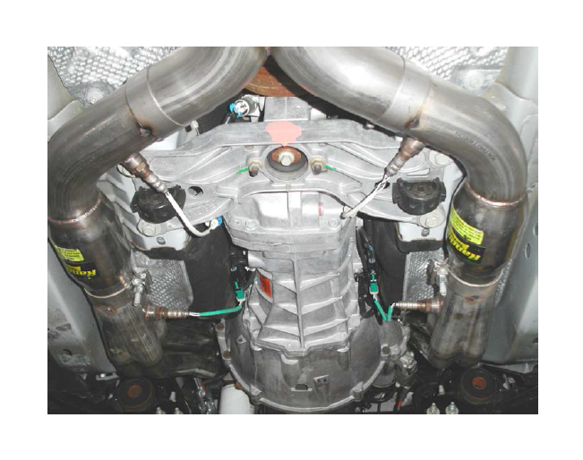
20. Note that the O2 sensors must be installed in the lead pipes before installing the
pipes in the system. Install the leadpipes with two 3” band clamps, and X-pipe.
Use wide OEM clamps to connect X-pipe to the exhaust system.
21. Once all pipes fit properly, we recommend breaking the exhaust apart and using
red high temp RTV at each joint to ensure a leak proof seal. Tighten all clamps
making sure that there is adequate clearance. The rear O2 wires can be pulled
down from the looms to reach the new O2 sensor locations. Reinstall the O2
sensors, using a small amount of never seize on the threads. Be sure to only apply
never seize to the threads-if this is applied to the O2 element it will ruin the O2
sensor. Zip tie the extender harnesses out of the way. Reconnect battery, start
car and warm up. Let cool thoroughly and retighten all header bolts and clamps.
Drive car and enjoy your new found power.