 FREE 1 to 3-Day Delivery on Orders $149+ Details
How to Install Wilwood Superlite 4R Road Race Front Brake Kit (05-14 All) on your Ford Mustang

Shop Parts in this Guide
Important Notice - Read This First
Before any tear-down or disassembly begins, review the following information:
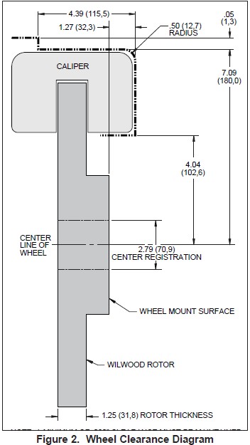
• Review the wheel clearance diagram (Figure 2, page 3) to verify that there is adequate clearance with the wheels you will be using with the installation.
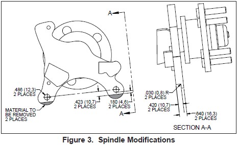
• There are spindle modifications that need to be performed before installation of the Wilwood caliper bracket. Please reference Figure 3, page 4. These modifications should be performed by a qualified machinist.
• Due to OEM production differences and other variations from vehicle to vehicle, the fastener hardware and other components in this kit may not be suitable for a specific application or vehicle.
• It is the responsibility of the purchaser and installer of this kit to verify suitability / fitment of all components and ensure all fasteners and hardware achieve complete and proper engagement. Improper or inadequate engagement can lead to component failure.
Photographic Tip
Important and highly recommended: Take photos of brake system before disassembly and during the disassembly process. In the event, trouble-shooting photos can be life savers. Many vehicles have undocumented variations, photos will make it much simpler for Wilwood to assist you if you have a problem.
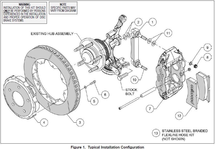
Exploded Assembly Diagram
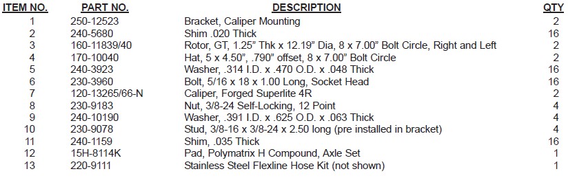
Parts List
General Information and Disassembly Instructions
• Installation of this kit should ONLY be performed by persons experienced in the installation and proper operation of disc brake systems. Before assembling this Wilwood front disc brake kit, double check the following to ensure a trouble free installation.
• Make sure this is the correct kit to fit the exact make and model year of your vehicle. This kit is designed for direct bolt-on installation to 2005 through present model year Mustang.
•Verify that the factory axle hub center register diameter and lug pattern match those in the new hat. NOTE: Axle hubs that have been modified with different size studs or lug patterns may require modifications to the new hat that must be performed by a qualified machinist.
•Verify your wheel clearance using Figure 2.
• Inspect the contents of this kit against the parts list to ensure that all components and hardware are included.
Disassembly Instructions
•Disassemble the original equipment front brakes: Raise the front wheels off the ground and support the front suspension according to the vehicle manufacturer’s instructions. Remove the front wheels, calipers, rotors, and dust shields. Save the Original Equipment Manufacturer (OEM) caliper mounting bolts.
•Remove any nicks or burrs on the axle hub and upright that may interfere with the installation of the new brake components.
•Clean and de-grease the axle hub, upright, and saved components.
Spindle Modifications
•These modifications should be performed by a qualified machinist. Refer to Figure 3, right. Only one view of the spindle is shown, but the modifications need to be performed on both spindles.
•The inboard side of the OE caliper mounting tabs need to be modified for proper installation of the new Wilwood caliper mounting bracket. Referring to the dimensiions in Figure 3, remove the shaded material from both mounting tabs. Be sure the area is free of sharp edges and burrs. Remove only the material indicated to clear the new caliper bracket.
Assembly Instructions
Assembly Instructions (numbers in parenthesis refer to the parts list and Figure 1 on the preceding pages):
• The caliper mount bracket (1) should initially be installed with clean, dry threads on the mounting bolts. Orient the bracket as shown in Figure 1 and Photo 1, then install using OEM mounting bolts. Initially place two .020” thick shims (2) on each bolt between the bracket and upright, Figure 1. Temporarily tighten the mounting bolts. NOTE: The bracket must fit squarely against the mount bosses on the upright. Inspect for interference from casting irregularities, machining ridges, burrs, etc. Later, after the caliper alignment has been checked, the mount bolts will be secured using red Loctite® 271.
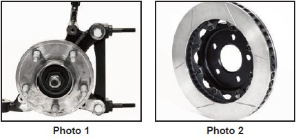
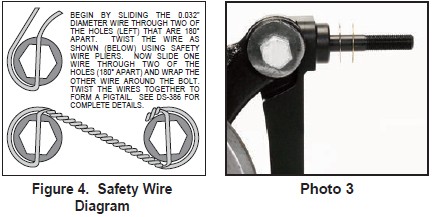
• Orient the rotor (3) and the hat (4) as shown in Figure 1 and Photo 2. Attach rotor to hat using bolts (6) and washers (5). Using an alternating sequence, apply red Loctite® 271 to the threads, and torque to 25 ft-lbs. For an added measure of security, the bolts may be safety wired using standard 0.032 inch diameter stainless steel safety wire as shown in Figure 4. Please refer to Wilwood’s data sheet DS-386 (available at www.wilwood.com/Pdf/DataSheets/ds386.pdf) for complete safety wire installation instructions.
• Slide the hat/rotor assembly onto the axle hub. NOTE: The hat must fit flush against the axle hub flange or excessive rotor run out may result. Install three lug nuts (finger tight) to keep the hat/rotor assembly in place while continuing with the installation.
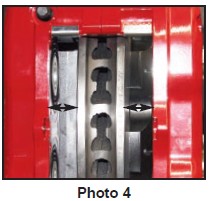
•NOTE: This kit contains distinct right and left hand calipers that must be mounted in a specific direction, as described below. Lubricate the caliper mounting studs (10) with lightweight oil. Initially place two .035” thick shims (11) on each stud between the caliper and the bracket, as shown in Figure 1 and Photo 3. With the bleed screws pointing up, mount the caliper (7) onto the bracket (1) using lock nuts (8) and washers (9), Figure 1. Temporarily tighten the lock nuts. Ensure that the caliper is mounted so the largest pistons are at the rotor exit end of the caliper, in relation to the direction of the rotor. View the rotor through the top opening of the caliper. The rotor should be centered in the caliper, Photo 4. If not, adjust by adding or subtracting shims (2) between the bracket and the upright. Always use the same amount of shims on each of the two mounting bolts. Once the caliper alignment is correct, remove the bracket mounting bolts one at a time, apply red Loctite® 271 to the threads, and torque to OEM manufacturer specifications.
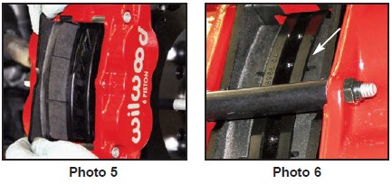
•Remove the caliper center bridge pad retainer bolt, nut, and tube from the caliper. Insert the brake pads (12) into the caliper, with the friction material facing the rotor, as shown in Photo 5. Check that the top of the brake pad is flush with the outside diameter of the rotor, Photo 6. If not, adjust by adding or subtracting shims (11) between the caliper and the bracket. After the caliper pad height is set, torque the caliper lock nuts (8) to 30 ft-lb. Secure the brake pads in place with the center bridge pad retainer tube, bolt, and locknut. The locknut should be snug without play in the bolt or tube. Be cautious not to over tighten.
•Temporarily install the wheel and torque the lug nuts to the manufacturer’s specification. Ensure that the wheel rotates freely without any interference.
•NOTE: The caliper in this brake kit utilizes a 1/8-27 NPT pipe thread inlet. OEM rubber brake hoses generally cannot be adapted to Wilwood calipers. Install Wilwood’s stainless steel braided flexline hose kit, P/N 220-9111 included with this kit. Carefully route hoses to prevent contact with moving suspension, brake or wheel components. NOTE: Wilwood hose kits are designed for use in many different vehicle applications and it is the installer's responsibility to properly route and ensure adequate clearance and retention for brake hose components.
•NOTE: Specified brake hose kits may not work with all Years, Makes and Models of vehicle that this brake kit is applicable to, due to possible OEM manufacturing changes during a production vehicle's life. It is the installer's responsibility to ensure that all fittings and hoses are the correct size and length, to ensure proper sealing and that they will not be subject to crimping, strain and abrasion from vibration or interference with suspension components, brake rotor or wheel.
•In absence of specific instructions for brake line routing, the installer must use his best professional judgment on correct routing and retention of lines to ensure safe operation. Test vehicle brake system per the 'minimum test' procedure stated within this document before driving. After road testing, inspect for leaks and interference. Initially after install and testing, perform frequent checks of the vehicle brake system and lines before driving, to confirm that there is no undue wear or interference not apparent from the initial test. Afterwards, perform periodic inspections for function, leaks and wear in a interval relative to the usage of vehicle.
• Bleed the brake system, referring to the additional information and recommendations on page 6 for proper bleeding instructions. Check system for leaks after bleeding.
•Install the wheel and torque the lug nuts to manufacturer’s specifications.
Additional Information and Recommendations
•Fill and bleed the new system with Wilwood Hi-Temp° 570 grade fluid or higher. For severe braking or sustained high heat operation, use Wilwood EXP 600 Plus Racing Brake Fluid. Used fluid must be completely flushed from the system to prevent contamination. NOTE: Silicone DOT 5 brake fluid is NOT recommended for racing or performance driving.
•To properly bleed the brake system, begin with the caliper farthest from the master cylinder. Bleed the outboard bleed screw first, then the inboard. Repeat the procedure until all calipers in the system are bled, ending with the caliper closest to the master cylinder. NOTE: When using a new master cylinder, it is important to bench bleed the master cylinder first.
•If the master cylinder is mounted lower than the disc brake calipers, some fluid flowback to the master cylinder reservoir may occur, creating a vacuum effect that retracts the caliper pistons into the housing. This will cause the pedal to go to the floor on the first stroke until it has “pumped up” and moved all the pistons out against the pad again. A Wilwood in-line two pound residual pressure valve, installed near the master cylinder will stop the fluid flowback and keep the pedal firm and responsive.
•Test the brake pedal. It should be firm, not spongy and stop at least 1 inch from the floor under heavy load. If the brake pedal is spongy, bleed the system again.
If the brake pedal is initially firm, but then sinks to the floor, check the system for fluid leaks. Correct the leaks (if applicable) and then bleed the system again.
If the brake pedal goes to the floor and continued bleeding of the system does not correct the problem, a master cylinder with increased capacity (larger bore diameter) will be required. Wilwood offers various lightweight master cylinders with large fluid displacement capacities.
•NOTE: With the installation of after market disc brakes, the wheel track may change depending on the application. Check your wheel offset before final assembly.
•On some models of disc brake spindles there are “ears” where the OEM calipers were mounted and these “ears” interfere with the assembly of the Wilwood disc brake kit. If it becomes necessary to remove these “ears”, remove as little as possible being careful not to cut away any of the mounting holes that may be required to bolt on the caliper mounting bracket.
•If after following the instructions, you still have difficulty in assembling or bleeding your Wilwood disc brakes, consult your local chassis builder, or retailer where the kit was purchased for further assistance.
Brake Testing
WARNING • DO NOT DRIVE ON UNTESTED BRAKES BRAKES MUST BE TESTED AFTER INSTALLATION OR MAINTENANCE MINIMUM TEST PROCEDURE
• Make sure pedal is firm: Hold firm pressure on pedal for several minutes, it should remain in position without sinking. If pedal sinks toward floor, check system for fluid leaks. DO NOT drive vehicle if pedal does not stay firm or can be pushed to the floor with normal pressure.
• At very low speed (2-5 mph) apply brakes hard several times while turning steering from full left to full right, repeat several times. Remove the wheels and check that components are not touching, rubbing, or leaking.
• Carefully examine all brake components, brake lines, and fittings for leaks and interference.
• Make sure there is no interference with wheels or suspension components.
• Drive vehicle at low speed (15-20 mph) making moderate and hard stops. Brakes should feel normal and positive. Again check for leaks and interference.
• Always test vehicle in a safe place where there is no danger to (or from) other people or vehicles.
• Always wear seat belts and make use of all safety equipment.
Pad and Rotor Bedding
BEDDING STEPS FOR NEW PADS AND ROTORS – ALL COMPOUNDS
Once the brake system has been tested and determined safe to operate the vehicle, follow these steps for the bedding of all new pad materials and rotors. These procedures should only be performed on a race track, or other safe location where you can safely and legally obtains speeds up to 65 MPH, while also being able to rapidly decelerate.
• Begin with a series of light decelerations to gradually build some heat in the brakes. Use an on-and-off the pedal technique by applying the brakes for 3-5 seconds, and then allow them to fully release for a period roughly twice as long as the deceleration cycle. If you use a 5 count during the deceleration interval, use a 10 count during the release to allow the heat to sink into the pads and rotors.
• After several cycles of light stops to begin warming the brakes, proceed with a series of medium to firm deceleration stops to continue raising the temperature level in the brakes.
• Finish the bedding cycle with a series of 8-10 hard decelerations from 55-65 MPH down to 25 MPH while allowing a proportionate release and heat-sinking interval between each stop. The pads should now be providing positive and consistent response.
• If any amount of brake fade is observed during the bed-in cycle, immediately begin the cool down cycle.
• Drive at a moderate cruising speed, with the least amount of brake contact possible, until most of the heat has dissipated from the brakes. Avoid sitting stopped with the brake pedal depressed to hold the car in place during this time. Park the vehicle and allow the brakes to cool to ambient air temperature.
COMPETITION VEHICLES
• If your race car is equipped with brake cooling ducts, blocking them will allow the pads and rotors to warm up quicker and speed up the bedding process.
• Temperature indicating paint on the rotor and pad edges can provide valuable data regarding observed temperatures during the bedding process and subsequent on-track sessions. This information can be highly beneficial when evaluating pad compounds and cooling efficiencies.
POST-BEDDING INSPECTION – ALL VEHICLES
• After the bedding cycle, the rotors should exhibit a uniformly burnished finish across the entire contact face. Any surface irregularities that appear as smearing or splotching on the rotor faces can be an indication that the brakes were brought up to temperature too quickly during the bedding cycle. If the smear doesn’t blend away after the next run-in cycle, or if chatter under braking results, sanding or resurfacing the rotors will be required to restore a uniform surface for pad contact.
PRE-RACE WARM UP
• Always make every effort to get heat into the brakes prior to each event. Use an on-and-off the pedal practice to warm the brakes during the trip to the staging zone, during parade laps before the flag drops, and every other opportunity in an effort to build heat in the pads and rotors. This will help to ensure best consistency, performance, and durability from your brakes.
DYNO BEDDED COMPETITION PADS AND ROTORS
• Getting track time for a proper pad and rotor bedding session can be difficult. Wilwood offers factory dyno-bedded pads and rotors on many of our popular competition pads and Spec 37 GT series rotors. Dyno-bedded parts are ready to race on their first warm up cycle. This can save valuable time and effort when on-track time is either too valuable or not available at all, Dyno-bedding assures that your pads and rotors have been properly run-in and are ready to go. Contact your dealer or the factory for more information on Wilwood Dyno-Bedding services.
NOTE: NEVER allow the contact surfaces of the pads or rotors to be contaminated with brake fluid. Always use a catch bottle with a hose to prevent fluid spill during all brake bleeding procedures.
