 FREE 1 to 3-Day Delivery on Orders $149+ Details
How to Install Maximum Motorsports Adjustable Clutch Pedal Stop (96-04 All) on your Ford Mustang

Shop Parts in this Guide
Tilton multi-disc racing clutches require a properly adjusted pedal stop to prevent damage to the clutch assembly. This adjustable pedal stop limits travel of the clutch pedal to prevent over-stroking the pressure plate. Specifically designed by MM to fit the stock clutch pedal of 1996-04 Mustangs. It must be adjusted to allow just enough pedal travel to disengage the clutch, but no more.
Improper adjustment will cause over-stroking, which in turn will cause significant damage to the clutch assembly because the throw-out bearing will push the diaphragm spring into the disc, damaging the diaphragm spring, the throw-out bearing, and bending the discs. The clutch will then not release, requiring replacement of all the damaged parts.
Read all instructions before beginning work. Following instructions in the proper sequence will ensure the best and easiest installation.
Supplemental Installation Notes
• The MMCL-21B requires the use of the MMCL3 Firewall Adjuster, when used with a cable operated clutch. Please install the MMCL-3 before continuing with these instructions.
• The MMCL-21B can be used with the MMCL-7 Pedal Height Adjuster. Install the Pedal Height Adjuster before continuing with these installation instructions
• If necessary, remove the driver side seat and mounting studs to ease installation of the MM Clutch Pedal Stop.
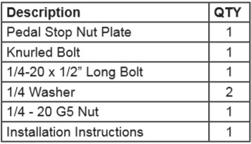
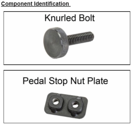
This Kit Contains
NOTE: These instructions assume the MM-Tilton Clutch Kit has already been installed.
NOTE: The photos below show the pedal box removed from the vehicle for clarity.
Installation
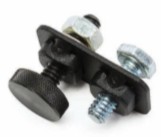
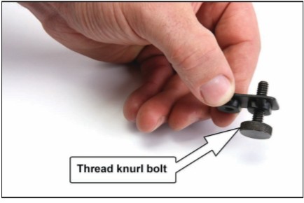
1. Thread the provided knurled bolt into the Pedal Stop Nut Plate. The knurled head should be on the same side as the welded-on nuts.
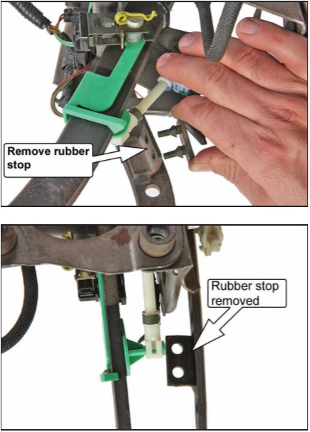
2. Remove the rubber pedal stop pad located on the clutch pedal.
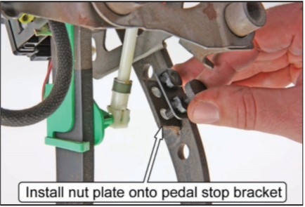
3. Place the Pedal Stop Nut Plate on the underside of the pedal stop bracket as shown below. The knurled bolt should be located in the lower hole of the pedal stop bracket.
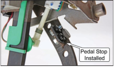
4. Using the provided 1/4-20 x 1/2” long bolt, with a washer under the head, secure the Pedal Stop Nut Plate to the pedal stop bracket. The bolt should pass through the upper mounting hole of the pedal stop bracket.
5. Torque the ¼-20 bolt to 7 lb-ft while making sure the knurled bolt can still rotate easily.
6. Place the provided ¼-20 nut and remaining washer on the knurled bolt and thread it down until it contacts the pedal stop bracket.
Clutch Cable Adjustment
7. Thread the firewall adjuster out from the firewall far enough to take up all slack in the clutch cable.
8. Apply 5 lbs of force to the clutch pedal pad and check that it does not move more than ½”. If it does, thread the firewall adjuster out further until the pedal pad movement is reduced to ½” or less.
Pedal Stop Adjustment
NOTE: If using an MMCL-7 Pedal Height Adjuster, make sure the pedal is at the desired height before continuing.
9. Safely support the rear of the car on jack stands.
10. A helper is required at this point. With the engine off, the car in gear and the parking brake off, slowly depress the clutch pedal until the driveshaft can be rotated by hand.
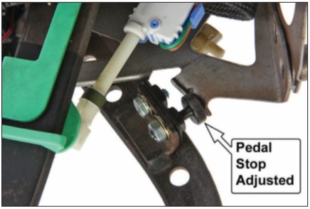
11. Push the pedal pad down an additional ¼” of travel (measured at the pedal pad). Thread out the knurled bolt until it contacts the bent flange on the pedal box. Release the pedal pad.
12. Tighten the ¼-20 nut against the pedal stop bracket.
13. Depress the clutch pedal until it hits the pedal stop and verify that the driveshaft can still be rotated. If not, repeat Steps 10-13.
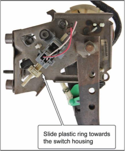
14. There is a clutch interlock switch located on the outboard side of the pedal box assembly that must be reset to allow the engine to crank. Locate the notched plastic shaft extending from the switch. On the shaft is a small plastic ring. With the clutch pedal up, slide the ring toward the switch housing until it touches.
15. Depress the clutch pedal to reset the interlock switch and attempt to start the vehicle. If the vehicle does not crank, repeat Step 14.
16. With the rear tires still off the ground, put the transmission in first gear. Depress the clutch pedal to disengage the clutch. Start the engine, keeping the clutch pedal fully depressed. If the rear wheels rotate when the clutch pedal is fully depressed, the clutch is not fully disengaged. Shut off the engine and adjust the clutch cable tension by turning the firewall adjuster to thread it out from the firewall. Do so in one-revolution increments, until the rear wheels do not rotate during the test of engine running, transmission in first gear, and clutch pedal fully depressed
17. Safely lower the vehicle back onto the ground and test drive.
