 FREE 1 to 3-Day Delivery on Orders $149+ Details
How to Install a Ford Racing 90mm Throttle Body on Your 2011-2014 Mustang GT

Shop Parts in this Guide
Please visit www.fordracingparts.com for the most current instruction information
! ! ! PLEASE READ ALL OF THE FOLLOWING INSTRUCTIONS CAREFULLY PRIOR TO INSTALLATION.
AT ANY TIME YOU DO NOT UNDERSTAND THE INSTRUCTIONS, PLEASE CALL THE FORD RACING TECHLINE AT 1-800-367-3788 ! ! !
! ! ! PLEASE READ THE FOLLOWING INSTRUCTIONS CAREFULLY PRIOR TO INSTALLATION ! ! !
____________________________________________________________________
Caution: If you are not confident that you can complete the installation safely, have it completed by a certified technician! Failure to complete the installation correctly could cause damage to your vehicle.
____________________________________________________________________
The following instructions apply to a 2011-2013 Mustang GT/2012-
2013 Boss 302 with stock 80mm throttle body.
Requires:
Adapter: M-9474-M50 For OEM Mustang GT 5.0L 4V TiVCT Intake
Adapter: M-9474-M50B for Ford Racing Boss Intake M-9424-M50BR
Silicone tube reducer 100mm to 88mm
----------------------------------------------------------------------------------------------------------------
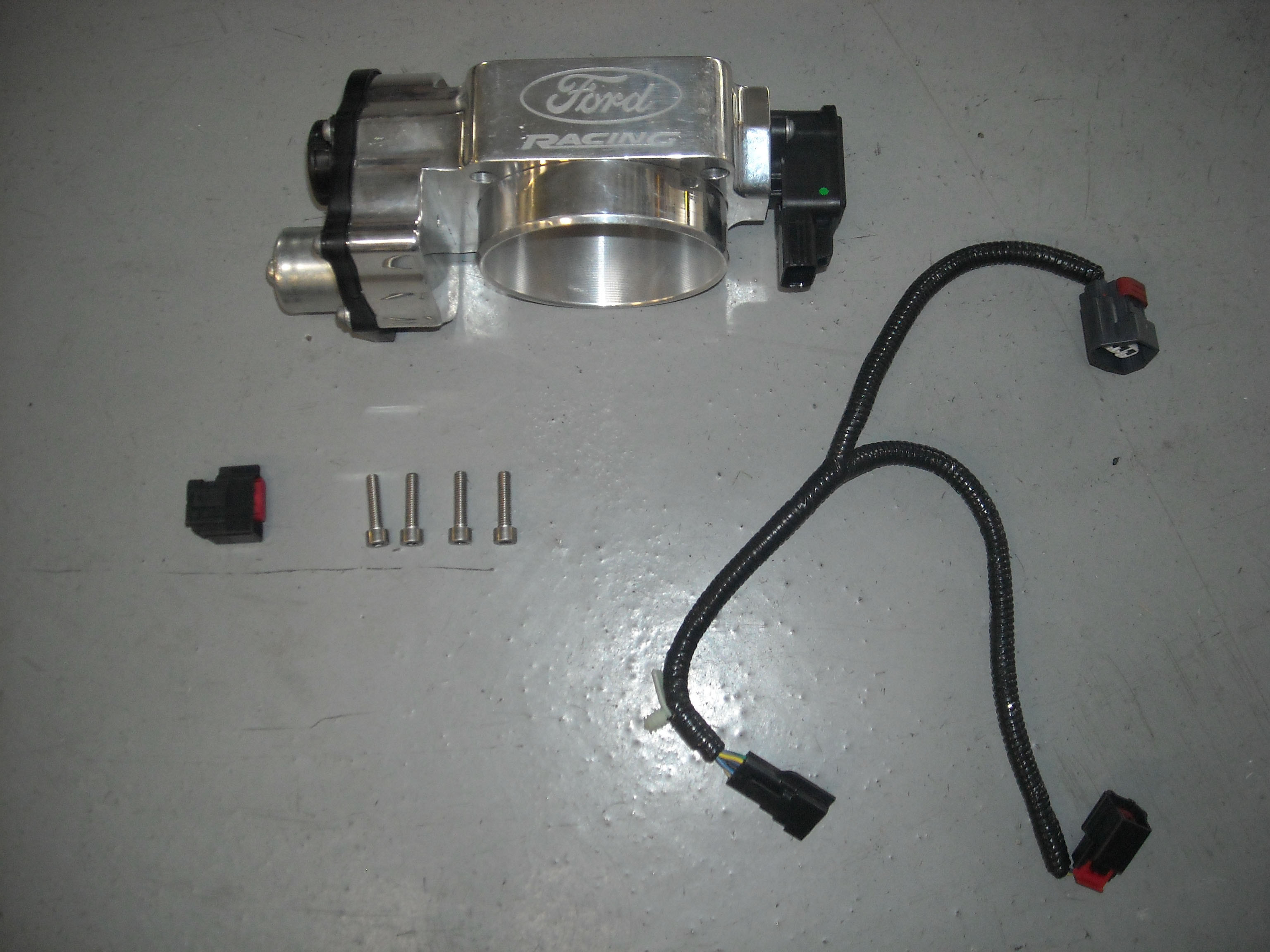
PARTS IN KIT:
Quantity Part Name
1 M-9926-M5090 Throttle Body
4 M6 X 40mm bolt
1 Jumper Harness
1 Harness Connector
INSTALLATION INSTRUCTIONS:
STEP 1: Disconnect the vehicles battery.
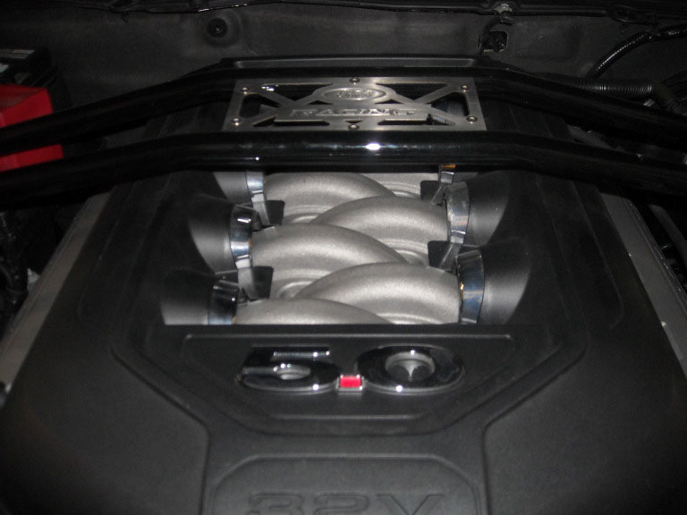
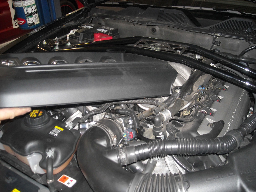
STEP 2: Remove engine cover by gently pulling upwards to unsnap.
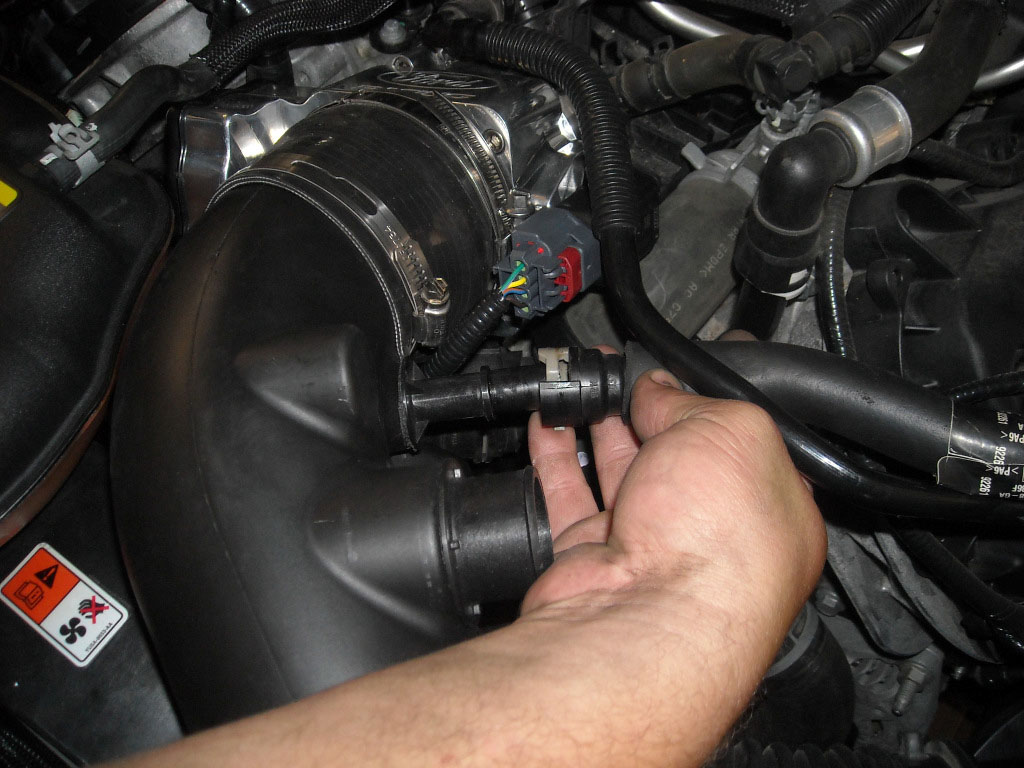
STEP 3: Remove intake cabin hose.
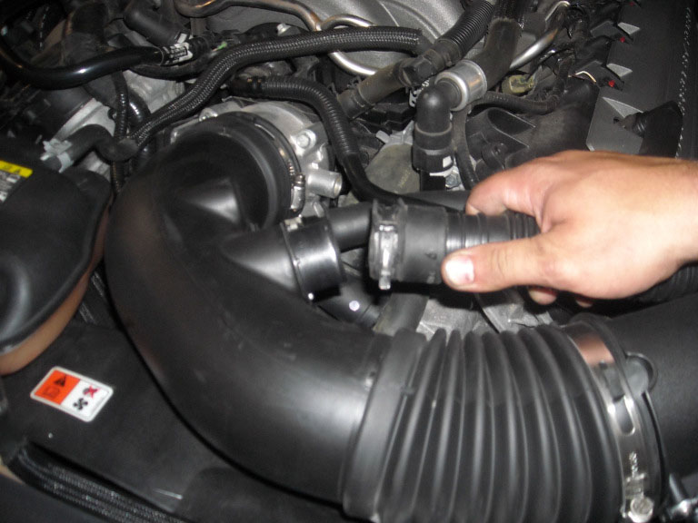
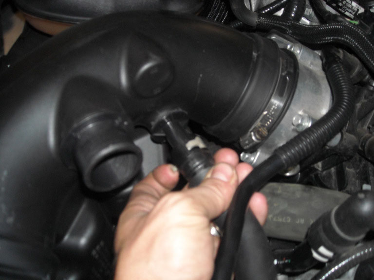
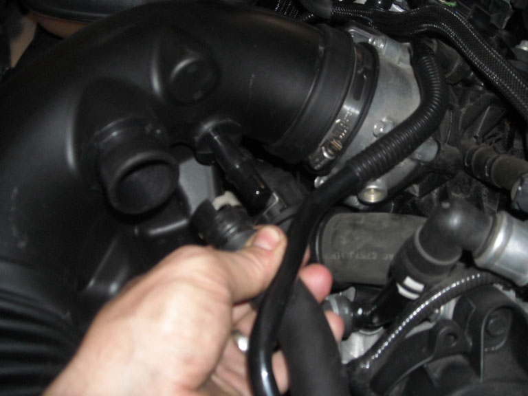
STEP 4: Unclip and remove breather tube.
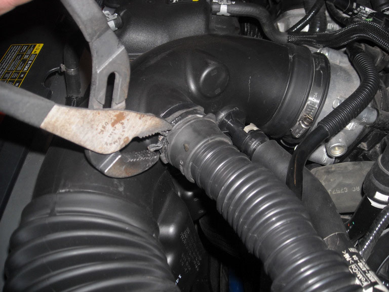
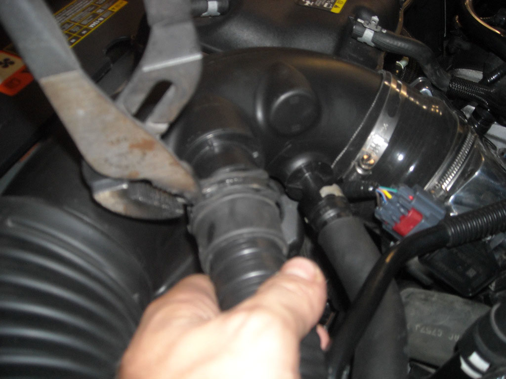
STEP 5: Loosen (2) hose clamps on intake tube.
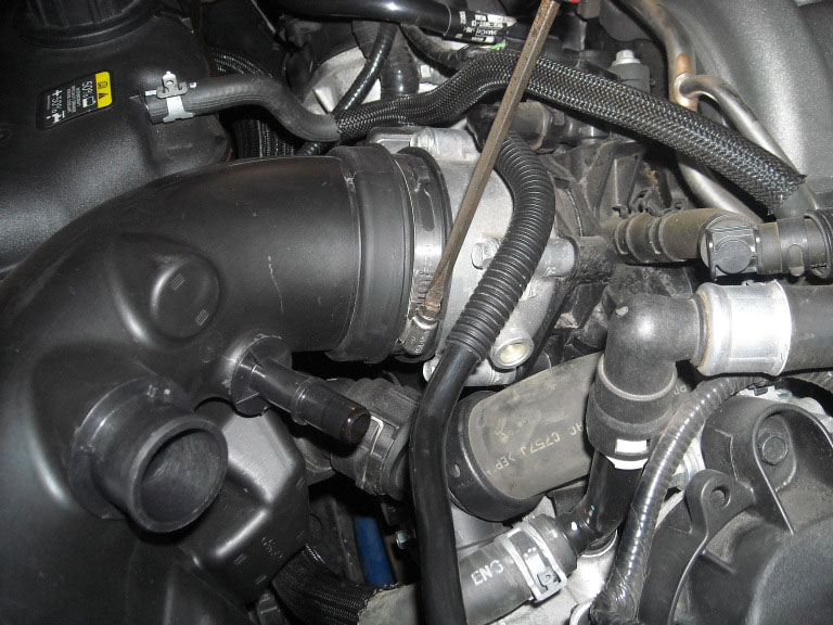
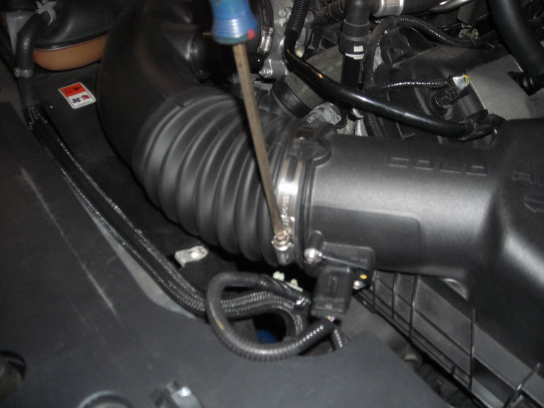
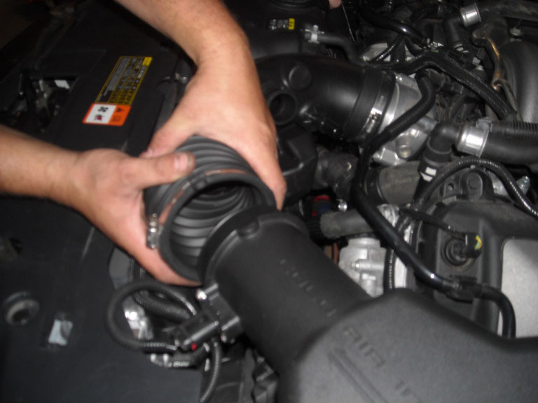
STEP 6: Remove the intake tube.
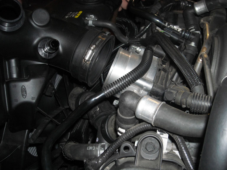
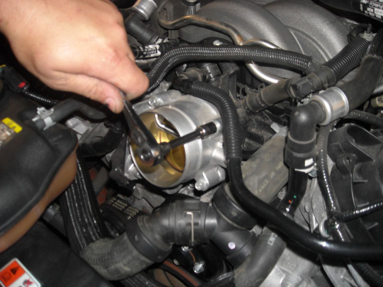
STEP 7: Unplug the throttle position sensor from throttle body.
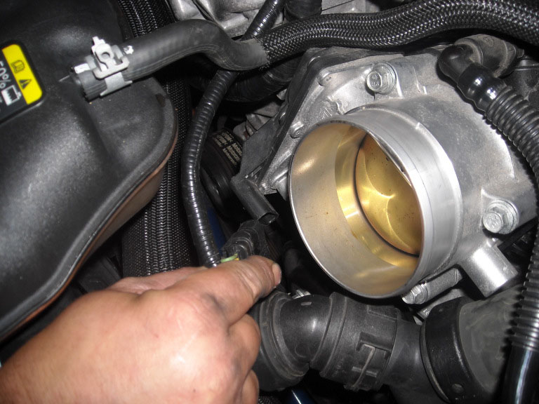
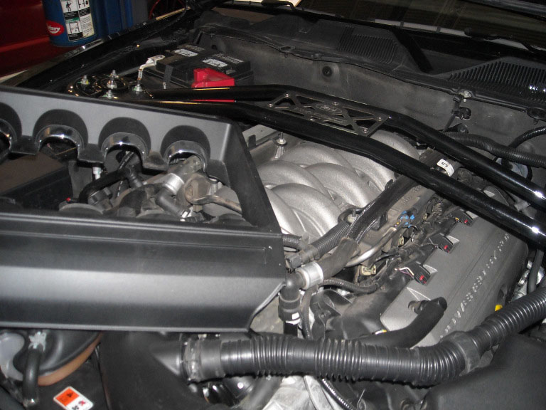
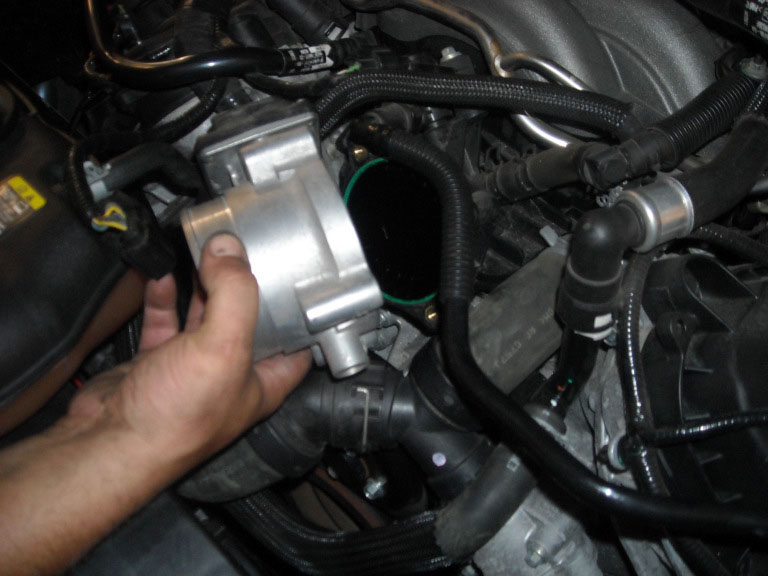
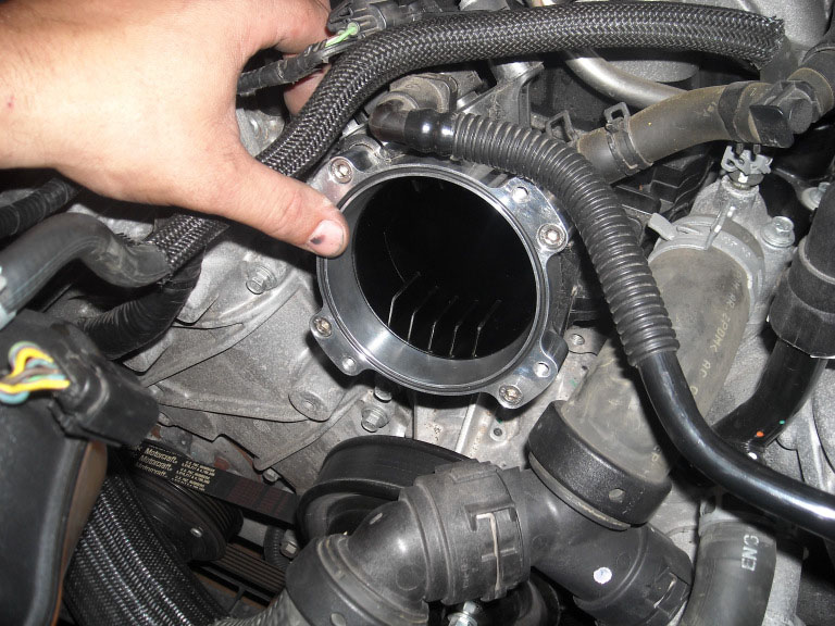
STEP 8: Remove (4) bolts attaching throttle body to intake manifold. Remove throttle body.
STEP 9: Install throttle body intake spacer M-9474-M50 or M-9474-M50B (Vehicle dependant). Tighten (4) bolts.
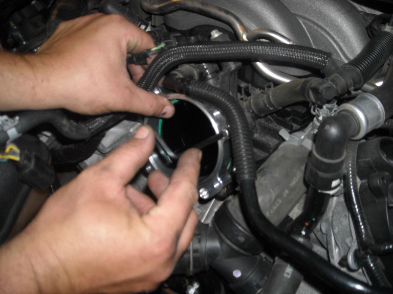
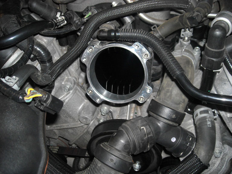
STEP 10: Install spacer O-ring supplied with M-9474-M50 or M-9474-M50B (Vehicle dependant).
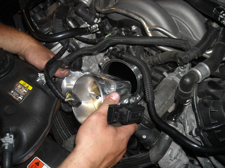
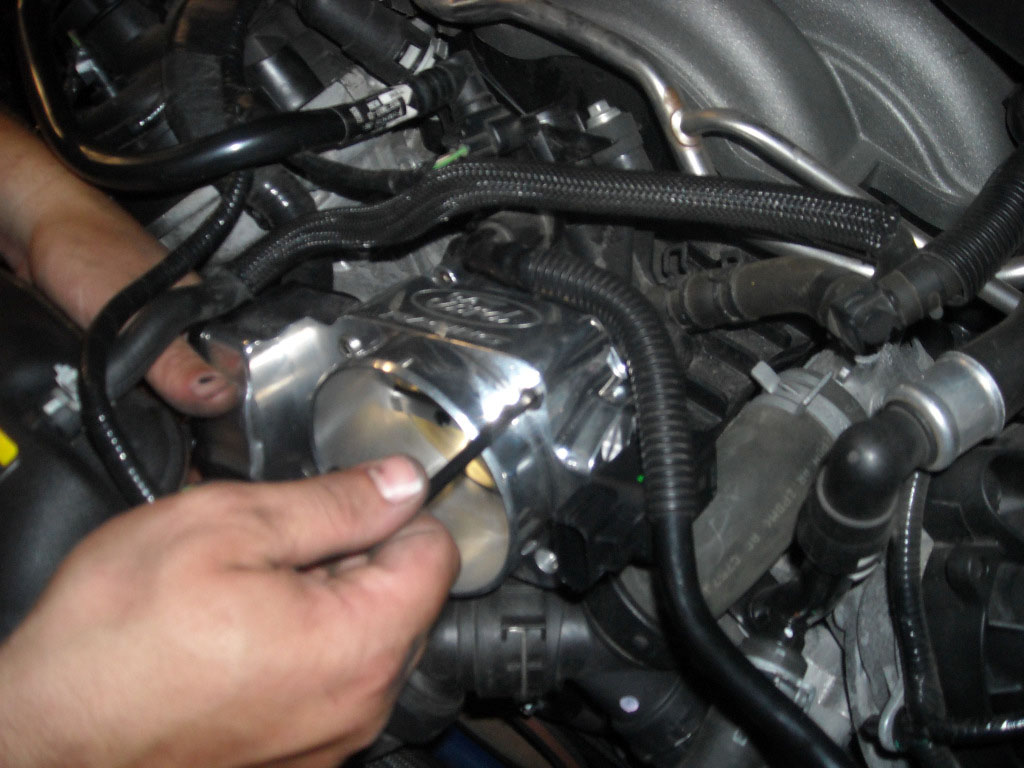
STEP 11: Install throttle body onto spacer and tighten (4) provided bolts.
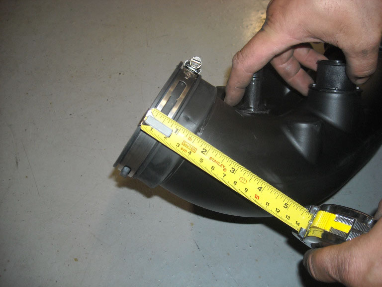
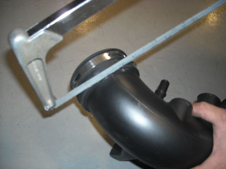
STEP 12: Cut the intake tube 1.50” from leading edge.
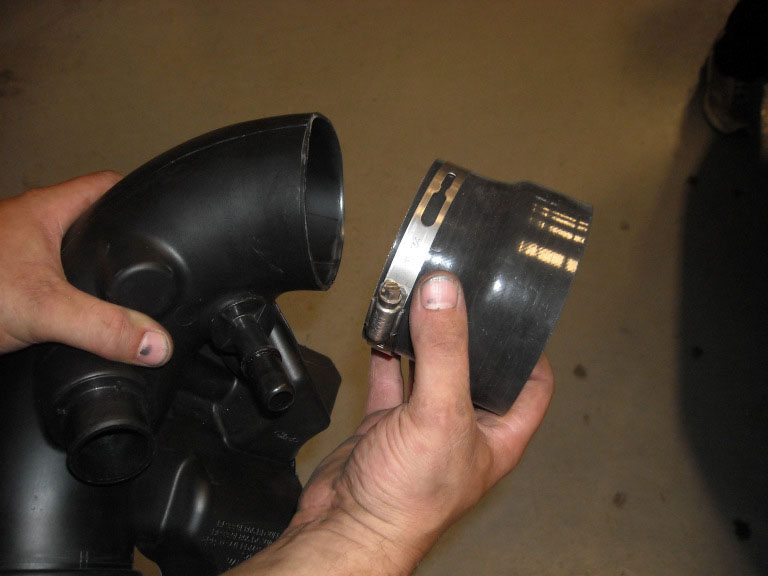
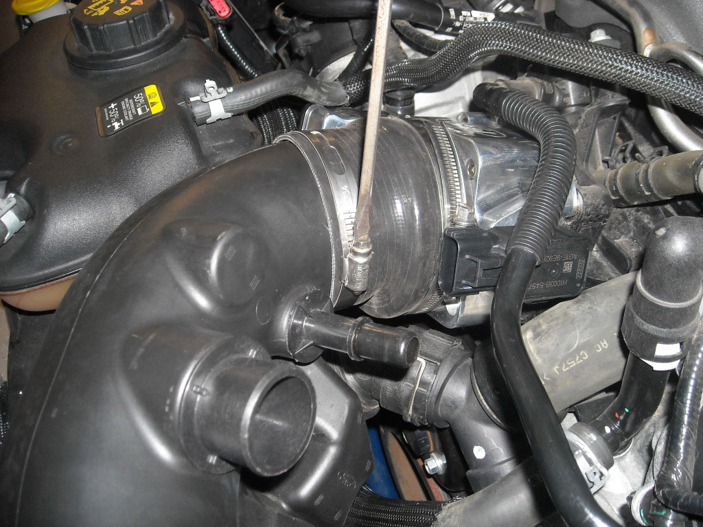
STEP 13: Install silicone reducer with hose clamps and tighten (Silicone reducer not included).
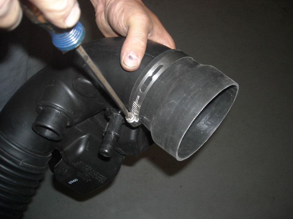
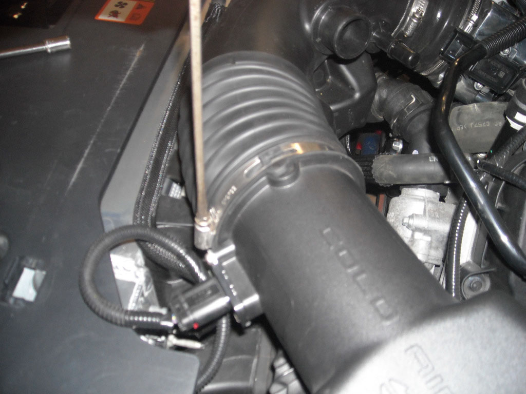
STEP 14: Reinstall modified intake tube onto throttle body and MAF housing.
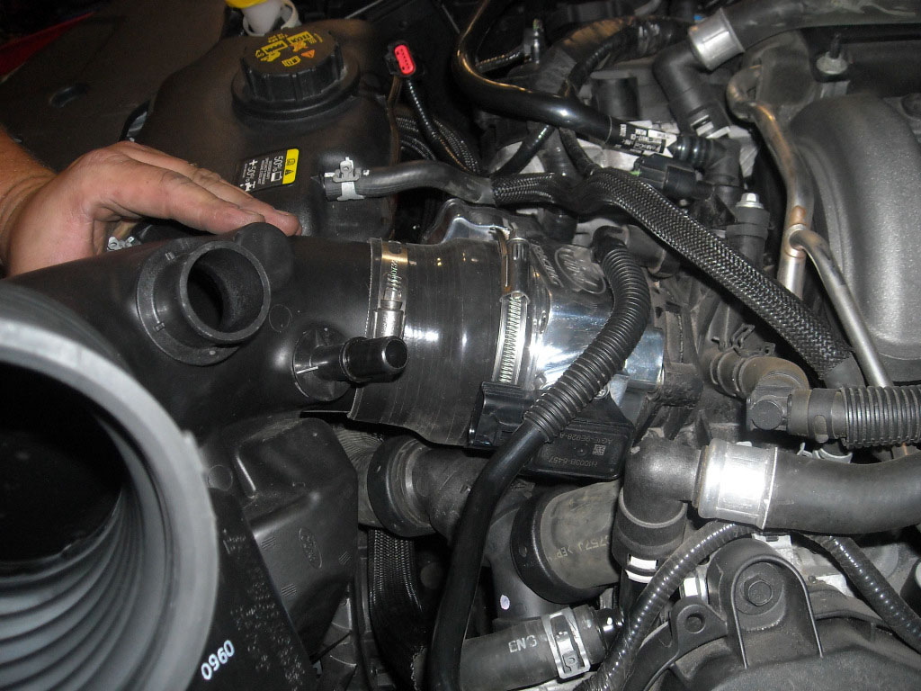
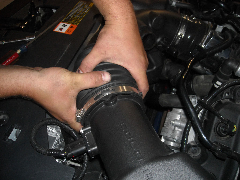
STEP 15: Tighten both hose clamps.
STEP 16: Replace the factory connector with the provided mating connector. Please review the following information before proceeding to step 17.
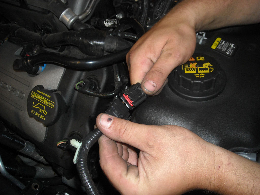
The factory harness connector will need to be replaced by using the new mating connector provided with the throttle body jumper harness. The location of the connector to be replaced is identified in Figure 1, referred to as C1449 (in RED).
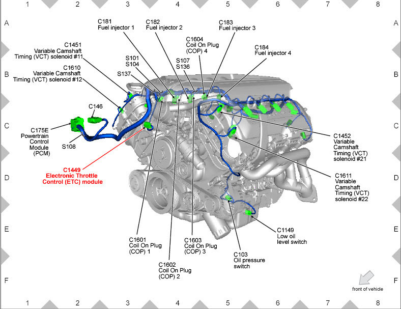
Figure 1
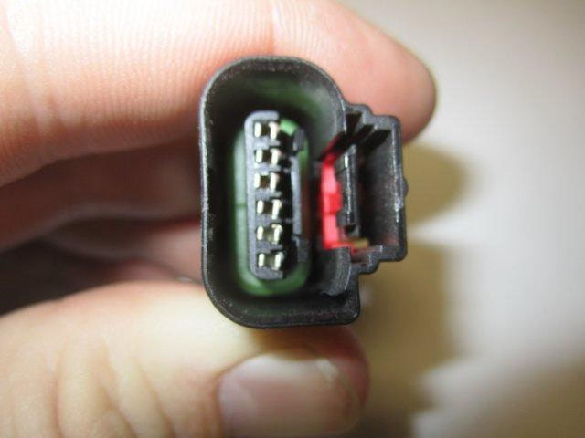
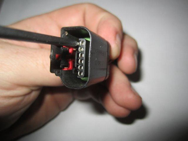
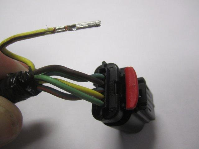
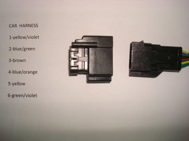
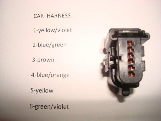
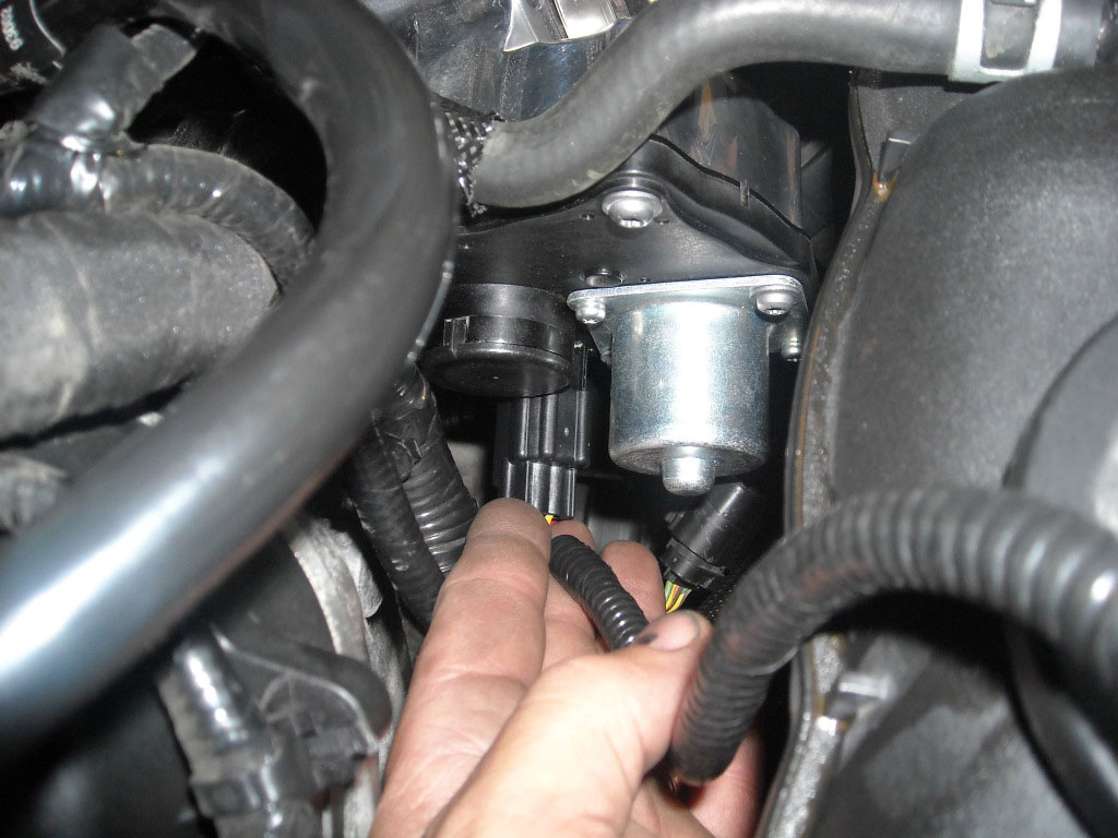
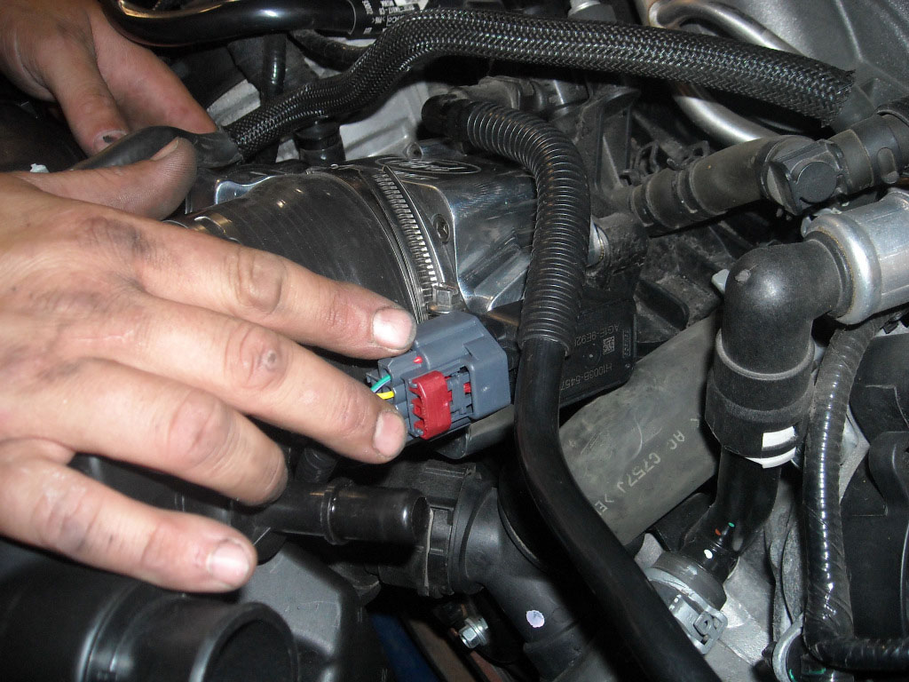
Identify the correct connector using Figure 2 below. This connector will be replaced with the connector shown in Figure 3
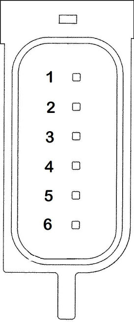
Figure 3 (Replacement Connector Face)
Replacing the Factory Harness Connector
The use of a pin extraction tool is recommended for this process. If you do not have a pin extraction tool, you may use a very thin screwdriver such as those used for repairing eyeglass frames.
TO INSURE THIS PROCEDURE IS DONE PROPERLY, IT IS HIGHLY RECOMMENDED TO SWAP ONLY ONE PIN AT A TIME!!
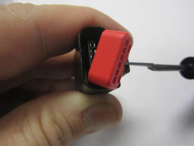
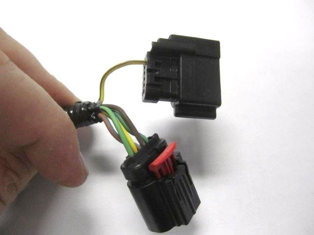
A: Unplug the factory connector from the throttle body. The red locking tab on the factory harness connector must be released to do this.
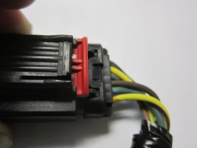
LOCKED
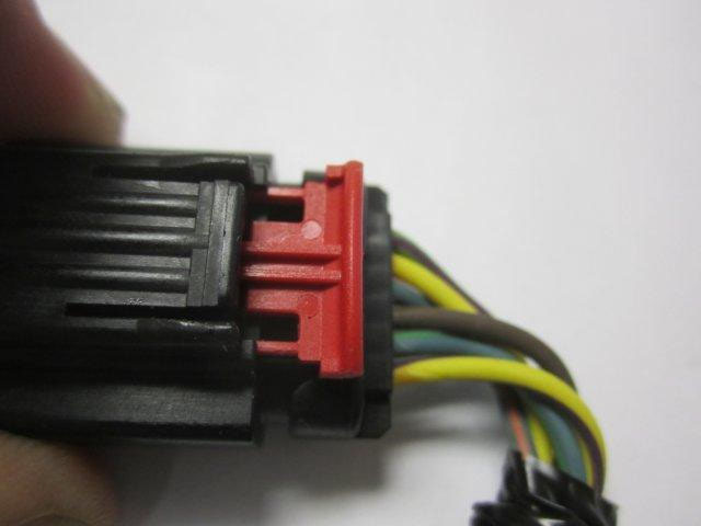
UNLOCKED
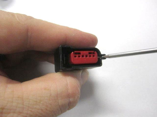
B: Gently pry the red retaining lock from the factory connector to reveal the female terminals.
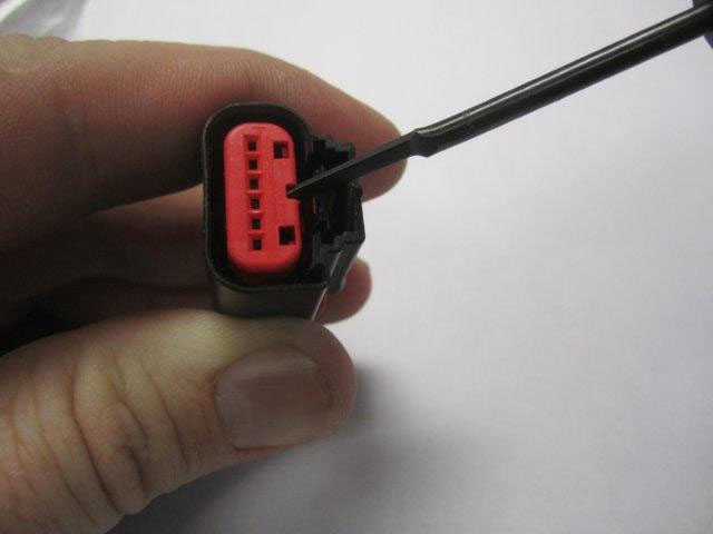
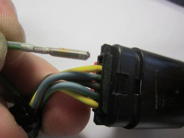
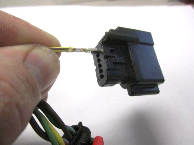
C: Starting with Pin 1, carefully pry back the plastic retaining tab (which holds the female terminal into the connector housing) while gently pulling on the wire from behind until the terminal has been released.
D: Completely remove the wire and terminal from the factory connector.
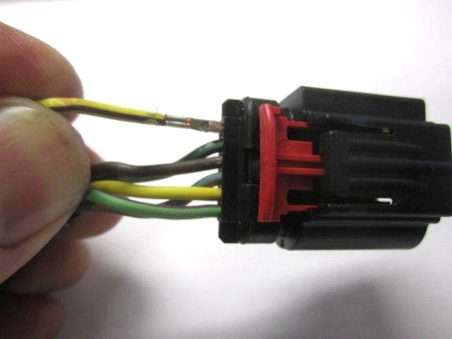
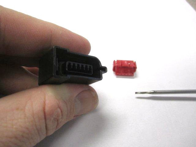
E: Prepare the NEW replacement connector for terminal insertion by removing the red retaining lock from the connector. Like the previous connector, this lock can also be removed by gently prying out.
F: Insert the terminal (from step D) into the NEW replacement connector noting the orientation of the terminal. A locating tab on the terminal will allow the terminal to insert in only one direction. DO NOT FORCE!
Note: When the terminal seats properly, you should hear a light clicking sound. Gently pull on the wire to
insure that it has seated properly into the NEW connector housing.
G: Return to Step C, and follow the same sequence for Pin 2 through Pin 6. Once all six terminals have been moved, replace the red locking tab (previously referred to in Step E).
H: After the NEW connector has been attached to the engine harness, connect the new jumper harness and route to the new throttle body’s Throttle Position Sensor (TPS) and Electronic Throttle Control (ETC) motor. There is a fir tree clip that will allow the harness to be securely fastened to the cylinder head.
When properly assembled, the factory wire colors should match the connector as follows:
STEP 17: Clip the provided jumper harness into the newly installed mating connector.
STEP 18: Clip the remaining (2) connectors on the jumper harness to the throttle body.
STEP 19: Reinstall the breather tube and cabin hose onto intake tube.
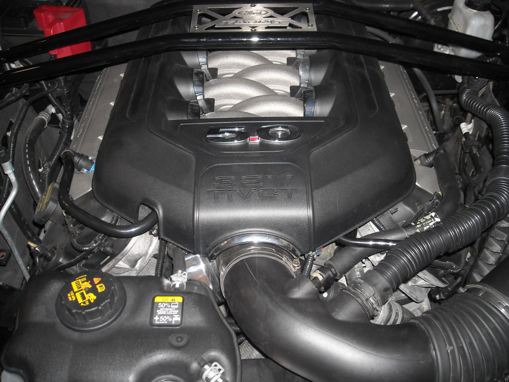
STEP 20: Reinstall engine cover and securely snap into place.
STEP 21: Connect battery.
