 FREE 1 to 3-Day Delivery on Orders $149+ Details
How To Install Vortech V-3 Si-Trim & Charge Cooler Complete Kit - Satin on your 2005-2008 Mustang GT
Installation Time
1 days
Tools Required
- Factory repair manual
- 3/8" socket and drive set: SAE & metric
- 1/2" socket and drive set: SAE & metric
- 3/8"NPT tap, 3/8-18 tap & handle
- Adjustable wrench
- Open end wrenches: 3/8", 7/16", 1/2", 9/16"
- Center punch and a 5/8" tapered punch
- 6 quarts (or what is specified in your owner’s manual) SF rated quality engine oil, oil filter and wrench
- If it has been 15,000 miles or more since your vehicle’s last spark plug change, then you will also need: • Spark plug socket • NEW spark plugs

Shop Parts in this Guide
Ford 4.6L 3V Mustang GT Supercharger System Installation Instructions
2005-2010 Model Year*50-State Smog Legal per C.A.R.B. EO #D-213-27
* 2007-2010 Models legal in California only for racing vehicles which may never be used upon a highway
Vortech Engineering
1650 Pacific Avenue, Channel Islands CA 93033-9901 • Phone: 805 247-0226Fax: 805 247-0669 • www.vortechsuperchargers.com • M-F 8:00AM - 4:30PM (PST)
©2010 b VORTECH ENGINEERING, LLC All rights reserved. No part of this publication may be reproduced, transmitted, transcribed, or translated into another language in any form, by any means without written permission of Vortech Engineering, LLC.
FOREWORD
This manual provides information on the installation, maintenance and service of the Vortech supercharger kit expressly designed for this vehicle. All information, illustrations and specifications contained herein are based on the latest product information available at the time of this publication. Changes to the manual may be made at any time without notice. Contact Vortech Engineering for any additional information regarding this kit and any of these modifications at (805) 247-0226 8:00am-4:30pm PST.
Take note of the following before proceeding:
1. Proper installation of this supercharger kit requires general automotive mechanic knowledge and experience. Please browse through each step of this instruction manual prior to beginning the installation to determine if you should refer the job to a professional installer/technician. Please contact your dealer or Vortech Engineering for possible installers in your area.
2. This product was designed for use on stock (un-modified, OEM) vehicles. The PCM (computer), engine, transmission, drive axle ratios and tire O.D. must be stock. If the vehicle or engine has been modified in any way, check with Vortech prior to installation and use of this product.
3. Use only premium grade fuel with a minimum of 91 octane (R M/2).
4. Always listen for any sign of detonation (knocking/pinging) and discontinue hard use (no boost) until problem is resolved.
5. Vortech is not responsible for any clutch, transmission, drive-line or engine damage.
Exclusions from Vortech warranty coverage considerations include, but not limited to:
1. Neglect, abuse, lack of maintenance, abnormal operation or improper installation.
2. Continued operation with an impaired vehicle or sub-system.
3. The combined use of Vortech components with other modifications such as, but not limited to, exhaust headers, aftermarket camshafts, nitrous oxide, third party PCM programming or other such changes.
TABLE OF CONTENTS
FOREWORD . . . . . . . . . . . . . . . . . . . . . . . . . . . . . . . . . . . . . . . . . . . . . . . . . . . . . . . . . ii
TABLE OF CONTENTS . . . . . . . . . . . . . . . . . . . . . . . . . . . . . . . . . . . . . . . . . . . . . . . . .
IMPORTANT NOTES . . . . . . . . . . . . . . . . . . . . . . . . . . . . . . . . . . . . . . . . . . . . . . . . . . iv
TOOL & SUPPLY REQUIREMENTS . . . . . . . . . . . . . . . . . . . . . . . . . . . . . . . . . . . . . . v
PARTS LIST (2005-2006 Mustang GT, Standard) . . . . . . . . . . . . . . . . . . . . . . . . . . . .vi
PARTS LIST (2005-2006 Mustang GT, Standard) Internally Lubricated . . . . . . . . . . .vii
PARTS LIST (2005-2006 Mustang GT, H.O.) . . . . . . . . . . . . . . . . . . . . . . . . . . . . . . . vii
PARTS LIST (2005-2006 Mustang GT, H.O.) Internally Lubricated . . . . . . . . . . . . . . . x
PARTS LIST (2007-2008 Mustang GT, Standard) . . . . . . . . . . . . . . . . . . . . . . . . . . . .ix
PARTS LIST (2007-2008 Mustang GT, Standard) Internally Lubricated . . . . . . . . . . xiii
PARTS LIST (2007-2008 Mustang GT, H.O.) . . . . . . . . . . . . . . . . . . . . . . . . . . . . . . . .x
PARTS LIST (2007-2008 Mustang GT, H.O.) Internally Lubricated . . . . . . . . . . . . . .xvi
PARTS LIST (2008 Mustang Bullitt) Internally Lubricated . . . . . . . . . . . . . . . . . . . . xviii
PARTS LIST (2010 Mustang GT, Standard) Internally Lubricated . . . . . . . . . . . . . . . xx
PARTS LIST (2010 Mustang GT, H.O.) Internally Lubricated . . . . . . . . . . . . . . . . . . xxii
1. PREPARATION/REMOVAL . . . . . . . . . . . . . . . . . . . . . . . . . . . . . . . . . . . . . . . . . . . 1
2. OIL FEED INSTALLATION . . . . . . . . . . . . . . . . . . . . . . . . . . . . . . . . . . . . . . . . . . . . 5
3. OIL DRAIN ASSEMBLY INSTALLATION . . . . . . . . . . . . . . . . . . . . . . . . . . . . . . . . . 6
4. POWER STEERING RELOCATION . . . . . . . . . . . . . . . . . . . . . . . . . . . . . . . . . . . . .7
4.1 POWER STEERING RELOCATION (2010 Only) . . . . . . . . . . . . . . . . . . . . . . . . . . 8
5.1 COOLANT TUBE RELOCATION (2005-2006 Only) . . . . . . . . . . . . . . . . . . . . . . . .9
5.2 THERMOSTAT HOUSING/RADIATOR HOSE MODIFICATION (2007-2010 Model Year Only) . . . . . . . . . . . . . . . . . . . . . . . . . . . . . . . . . . . . . . . . . . . . . . . . . . . . . . . . . . 12
6.1 PULLEY AND SPACER REPLACEMENT (Bullet/V-Power Only) . . . . . . . . . . . . .14
6.2 SUPERCHARGER MOUNTING PLATE INSTALLATION . . . . . . . . . . . . . . . . . . .18
7. THERMOSTAT HOUSING RELOCATION (2005-2006 Only) . . . . . . . . . . . . . . . . .21
8. CHARGE AIR COOLER INSTALLATION (H.O. Kits Only) . . . . . . . . . . . . . . . . . . .23
8.A BUMPER COVER AND SPLASH PAN . . . . . . . . . . . . . . . . . . . . . . . . . . . . . . . . .23
8.B CHARGE AIR COOLER ASSEMBLY INSTALLATION (H.O. Kits Only) . . . . . . . .26
8.C ENGINE COOLANT RESERVOIR INSTALLATION (2005-2006 Models Only) . . 34
8.D RADIATOR HOSE MODIFICATIONS (2005-2006 Models Only) . . . . . . . . . . . . .37
8.E ENGINE COOLANT RESERVOIR INSTALLATION (2007-2010 Models Only) . . 38
8.F COOLER CORE INSTALLATION . . . . . . . . . . . . . . . . . . . . . . . . . . . . . . . . . . . . .41
8.G COOLANT RESERVOIR FILL . . . . . . . . . . . . . . . . . . . . . . . . . . . . . . . . . . . . . . . 42
8.1 2010 MUSTANG BUMPER TRIMMING (2010 Models Only) . . . . . . . . . . . . . . . . 43
8.2 COMPRESSOR BYPASS VALVE ASSEMBLY INSTALLATION . . . . . . . . . . . . . 45
8.3 COMPRESSOR BYPASS VALVE ASSEMBLY INSTALLATION (V-Power/Bullitt)46
9. AIR DISCHARGE ASSEMBLY (Non-cooled Kits Only) . . . . . . . . . . . . . . . . . . . . . .47
10. COMPRESSOR BY-PASS VALVE INSTALLATION (Non-cooled kits only) . . . . .48
11. COOLANT RESERVOIR RE-INSTALLATION (Non-cooled Kits Only) . . . . . . . . .49
12. CRANK CASE BREATHER AND PCV INSTALLATION . . . . . . . . . . . . . . . . . . . .50
13. AIR INLET ASSEMBLY . . . . . . . . . . . . . . . . . . . . . . . . . . . . . . . . . . . . . . . . . . . . .51
14. FUEL PUMP UPGRADE . . . . . . . . . . . . . . . . . . . . . . . . . . . . . . . . . . . . . . . . . . . .54
15. REFLASH COMPUTER . . . . . . . . . . . . . . . . . . . . . . . . . . . . . . . . . . . . . . . . . . . . .57
16. FINAL CHECK . . . . . . . . . . . . . . . . . . . . . . . . . . . . . . . . . . . . . . . . . . . . . . . . . . . .58
NOTICE
This product is protected by state common law, copyright and/or patent. All legal rights therein are reserved. The design, layout, dimensions, geometry, and engineering features shown in this product are the exclusive property of Vortech Engineering, LLC. This product may not be copied or duplicated in whole or part, abstractly or fundamentally, intentionally or fortuitously, nor shall any design, dimension, or other information be incorporated into any product or apparatus without prior written consent of Vortech Engineering, LLC.
2005-2010 Mustang GT Installation Instructions
Congratulations on selecting the best performing and best backed automotivesupercharger available today... the VORTECH® supercharger!
Before beginning this installation, please read through this entire instruction booklet and the Street Supercharger System Owner’s Manual which includes the Limited Warranty Program, the Warranty Registration form and return envelope.
Vortech supercharger systems are performance improving devices. In most cases, increases in torque of 30-35% and horsepower between 35-45% can be expected with the boost levels specified by Vortech Engineering. This product is intended for use on healthy, well maintained engines. Installation on a worn-out or damaged engine is not recommended and may result in failure of the engine as well as the supercharger. Vortech Engineering is not responsible for engine damage.
Installation on new vehicles will not harm or adversely affect the break-in period so long as factory break-in procedures are followed.
For best performance and continued durability, please take note of the following key points:
1. Use only premium grade fuel 91 octane or higher (R M/2).
2. The engine must have stock compression ratio.
3. If the engine has been modified in any way, check with Vortech prior to using this product.
4. Always listen for any sign of detonation (pinging) and discontinue hard use (no boost) until problem is resolved.
5. Perform an oil and filter change upon completion of this installation and prior to test driving your vehicle. Thereafter, always use a high grade SF rated engine oil or a high quality synthetic, and change the oil and filter at least every 3,000 miles. Never attempt to extend the oil change interval beyond 3,000 miles, regardless of oil manufacturer’s claims as potential damage to the supercharger may result.
6. Before beginning installation, replace all spark plugs that are older than 1-year or 15,000 miles with original heat range plugs as specified by the manufacturer and reset timing to factory specifications (follow the procedures indicated within the factory repair manual and/or as indicated on the factory underhood emissions tag). Do not use platinum spark plugs unless they are original equipment. Change spark plugs every 20,000 miles.
TOOL & SUPPLY REQUIREMENTS
• Factory repair manual
• 3/8" socket and drive set: SAE & metric
• 1/2" socket and drive set: SAE & metric
• 3/8"NPT tap, 3/8-18 tap & handle
• Adjustable wrench
• Open end wrenches: 3/8", 7/16", 1/2", 9/16"
• Center punch and a 5/8" tapered punch
• 6 quarts (or what is specified in your owner’s manual) SF rated quality engine oil, oil filter and wrench
If it has been 15,000 miles or more since your vehicle’s last spark plug change, then you will also need:
• Spark plug socket
• NEW spark plugs
PARTS LIST - 2005-2006 Mustang GT, Standard Part No. 4FU218-010SQ/018SQ
2E229-230 V2-S SUPERCHARGER ASY 1
4FU130-036 OIL DRAIN ASSY 1
7U030-036 1/2" OIL DRAIN HOSE 2.5
7R001-008 #8 HOSE CLAMP 2
7P375-017 3/8NPT X 1/2 BEADED HSE BRB 1
4FU130-026 OIL FEED ASY 1
7U250-090-260 OIL FEED HOSE, 26" -4X90° 1
7P125-005 1/8 NPT STR. X -4 JIC FTG STL 1
7P250-091 1/4 NPT 90° X -4JIC FTG STL 1
7P250-034 1/4 NPT X 1/4 NPT STRT T 1
4FU112-020 DISCHARGE ASY 1
4FU012-020 DUCT, DISCH, MUST GT STD 1
7S450-200 SLEEVE, 4 1/2 X 2, BLUE 1
7S300-276 REDUCER, 3.0 X 2.75 X 2.5L 1
7R002-044 #44 HOSE CLAMP 1
7R002-048 #48 HOSE CLAMP 1
7R002-072 #72 HOSE CLAMP 2
7R002-016 #16 HOSE CLAMP 4
7U030-046 5/32" VACUUM LINE 5
8D001-001 STD COMPRESS BYPASS VALVE 1
7U034-016 1" GS HEATER HOSE 1.25
7U034-016 1" GS HEATER HOSE 0.583
7P218-156 VAC TEE, 7/32,7/32,5/32 1
4FU112-010 AIR INTAKE ASY 1
4FU012-010 INLET DUCT,"A" 1
4FU012-015 INLET DUCT,"B" 1
7R002-056 #56 HOSE CLAMP 1
7S400-200 SLEEVE, 4 X 2, BLUE 2
7S400-351 REDUCER SLV 4.00 X 3.5 X 2.35L 1
7R002-064 #64 HOSE CLAMP 5
8H040-235 AIR FILTER, 4.0FLG X 7.0L 1
8A003-071 MAF, 3.8 I.D. MUSTANG GT 1
7P750-102 3/4NPT X 1" X 90° HSE FIT 1
7P250-047 1/4NPT TO 3/8"BARB 90° 1
4FU010-071 BRKT, INTAKE SUPPORT 1
7U032-016 3/8" EFI FUEL HSE HI-PSR 4
4FU013-010 COVER, AIR FILTER, MUST GT 1
7C040-008 M4-.7X8MM SCHD SS 2
4FU111-044 S/C MOUNTING BRKT ASY 1
4FU010-044 S/C MOUNT PLT, MUST GT 1
4FU010-034 IDLER MOUNT PLATE, MUST 1
4FU017-011 SPACER, STUDDED MUST GT 2
2A017-750-05 SPACER, .750 OD X 2.691 LONG 2
2A017-750-06 SPACER, .750 OD X 2.712 LONG 1
2A017-879-08 SPACER, .875 OD X 1.776 LONG 1
2A017-750-07 SPACER, .750 OD X .097 LONG 1
4FU017-021 SPACER, IDLER, MUST GT 1
4PCS016-160 PULLEY, IDLER 1
2A046-120 BELT, GATES K061203 1
7A375-375 3/8-16 X 3-3/4 HX HD 1
7C080-150 M8 X 1.25 X 150MM HXHD CL10.9 1
7C080-140 M8 X 1.25 X 140 HXHD CL8.8 2
7A375-100 3/8-16 X 1 G5 HHCS, PLT 7
7K312-030 5/16 AN WASHER, S.S. 2
7K375-040 3/8 AN960 FLAT WASHR PLATED 10
4FU139-096 PCV MOD ASY 1
7P375-106 PCV VALVE, FORD, 3/8" HOSE 1
7P625-377 5/8" -3/8" REDUCER BARB UNION 1
7R004-002 STEPLESS CLAMP, 17.0-70 2
7R004-004 STEPLESS CLAMP, 1.0 OD HOSE 3
7R004-007 STEPLESS CLAMP, 28.6 X 7MM WID 1
7U032-016 3/8" EFI FUEL HSE HI-PSR 0.25
7U033-020 HOSE, 5/8"ID CLASS 1 EMISSIONS 0.66667
4FU214-021 COOL BYP HOSE RELOC ASY 1
4FU114-021 ASY, WATER OUTLET, 05 MUST GT 1
7J875-010 7/8 SEALING WASHER 1
7F875-010 NUT, 7/8-14, SHORT/JAM 1
7U133-050 1.5" X 90° HOSE, LONG LEG 1
7U133-190 HOSE, COOLNT DRIV SIDE 05 MUST 1
7U038-000 3/4" HEATER HOSE 3.5
7P375-075 3/4" HOSE BARB UNION, BRASS 1
7R002-020 #20 HOSE CLAMP 4
7R002-024 #24 HOSE CLAMP 2
7P125-002 FREEZE PLUG, 1.25 DIA, .25 TAL 1
7R002-010 #10 HOSE CLAMP 4
7P125-016 1/8 NPT PLUG 1
4FU110-010 P/S RESERVOIR RELOCATION 1
7P375-075 3/4" HOSE BARB UNION, BRASS 1
7P375-050 3/8" HOSE UNION, BRASS 1
7R001-004 #4 HOSE CLAMP 2
7R001-008 #8 HOSE CLAMP 2
7U038-030 HOSE, P/S, 3/4 ID 3
7U032-016 3/8" EFI FUEL HSE HI-PSR 3
7A250-075 1/4-20 X .75 SHCS PLTD 1
7J250-001 1/4 WASHER, SAE, PLTD 2
7F250-021 1/4-20 NYLOCK NUT ZINC PLATED 1
4FU010-010 P/S RELOC BRKT, 05 GT MUST 1
7U100-055 TIE WRAP, 7.5" NYLON 4
8F060-048 FUEL INJ, 39LB EV6, OEM 03 COB 8
008110 SMALL SILVER DIE CUT DECAL 2
008444 3 YR S/C WARRANTY PKG 1
008130 LICENSE PLATE FRAME, VORTECH 1
4FU020-010 INSTR MAN 05-08 MUST GT 1
5A003-035 PREDATOR, 05-08 MUSTANG 1
8F101-262 FUEL PMP ASY,05 MUST TWIN INTA 1
7U032-018 3/8" SUBMERSIBLE EFI FUEL HOSE 2.75
7U100-055 TIE WRAP, 7.5" NYLON 4
7R004-002 STEPLESS CLAMP, 17.0-70 2
8F001-255 255 INTANK FUEL PUMP '86-'97 1
7R002-044 #44 HOSE CLAMP 1
7R004-006 STEPLESS CLAMP, 11.3 X 5MM WID 4
5W001-022 T-TAP CONN,14-16 AWG 2
5W001-009 16-14GA MALE SLIDE INSULATED 2
5W001-080 FUSE, 20 AMP. MINI BLADE 1
7P375-099 Y-UNION, 3/8" BARBED TEFLON 1
7U032-025 HOSE, 5/16" ID,3/8"OD, 1/32" W 0.125
7U032-030 HOSE,SPIRAL 3/8" CUFF ID, 1' L 2
4FU101-001 MAF EXT MOD 05 MUSTANG 1
5W018-030 18GA STRD WIRE GREY 1
5W018-010 18GA STRD WIRE RED 1
5W018-020 18GA STRD WIRE BLK, UL1015 1
5W018-080 18GA STRD WIRE BLUE BULK 1
5W018-090 18GA STRD WIRE BROWN BULK 1
5W018-100 18GA STRD WIRE PURPLE 1
5W001-007 3/16" HEAT-SHRINK TUBING 1.5
5W001-005 3/8" PLASTIC WIRE LOOM 1.5
5W001-012 18-22 GA BUTT CONN RED INSUL 12
Part No. 4FU218-010L/018L PARTS LIST
008110 SMALL SILVER DIE CUT DECAL 2
008130 LICENSE PLATE FRAME 1
008447 1 YR S/C WARRANTY PKG 1
009035 S/C LUBE, BOTTLED, 3-PACK 1
2F329-010 V3 SUPERCHARGER ASY, STD 1
4FU020-010 INSTR MAN 05-08 MUST GT 1
4FU110-010 P/S RESERVOIR RELOCATION 1
7P375-075 3/4" HOSE BARB UNION, BRASS 1
7P375-050 3/8" HOSE UNION, BRASS 1
7R001-004 #4 HOSE CLAMP 2
7R001-008 #8 HOSE CLAMP 2
7U038-030 HOSE, P/S, 3/4 ID 3
7U032-016 3/8" EFI FUEL HSE HI-PSR 3
7A250-075 1/4-20 X .75 SHCS PLTD 1
7J250-001 1/4 WASHER, SAE, PLTD 2
7F250-021 1/4-20 NYLOCK NUT ZINC PLATED 1
4FU010-010 P/S RELOC BRKT, 05 GT MUST 1
7U100-055 TIE WRAP, 7.5" NYLON 4
4FU111-044 S/C MOUNTING BRKT ASY 1
4FU010-044 S/C MOUNT PLT, MUST GT 1
4FU010-034 IDLER MOUNT PLATE, MUST 1
4FU017-011 SPACER, STUDDED MUST GT 2
2A017-750-05 SPACER, .750 OD X 2.691 LONG 2
2A017-750-06 SPACER, .750 OD X 2.712 LONG 1
2A017-879-08 SPACER, .875 OD X 1.776 LONG 1
2A017-750-07 SPACER, .750 OD X .097 LONG 1
4FU017-021 SPACER, IDLER, MUST GT 1
4PCS016-160 PULLEY, IDLER 1
2A046-120 BELT, GATES K061203 1
7A375-375 3/8-16 X 3-3/4 HX HD 1
7C080-150 M8 X 1.25 X 150MM HXHD CL10.9 1
7C080-140 M8 X 1.25 X 140 HXHD CL8.8 2
7A375-100 3/8-16 X 1 G5 HHCS, PLT 7
7K312-030 5/16 AN WASHER, S.S. 2
7K375-040 3/8 AN960 FLAT WASHR PLATED 10
4FU112-010 AIR INTAKE ASY 1
4FU012-010 INLET DUCT,"A" 1
4FU012-015 INLET DUCT,"B" 1
7R002-056 #56 HOSE CLAMP 1
7S400-200 SLEEVE, 4 X 2, BLUE 2
7S400-351 REDUCER SLV 4.00 X 3.5 X 2.35L 1
7R002-064 #64 HOSE CLAMP 5
8H040-235 AIR FILTER, 4.0FLG X 7.0L 1
8A003-071 MAF, 3.8 I.D. MUSTANG GT 1
7P750-102 3/4NPT X 1" X 90° HSE FIT 1
7P250-047 1/4NPT TO 3/8"BARB 90° 1
4FU010-071 BRKT, INTAKE SUPPORT 1
7U032-016 3/8" EFI FUEL HSE HI-PSR 4
4FU013-010 COVER, AIR FILTER, MUST GT 1
7C040-008 M4-.7X8MM SCHD SS 2
4FU112-020 DISCHARGE ASY 1
4FU012-020 DUCT, DISCH, MUST GT STD 1
7S450-200 SLEEVE, 4 1/2 X 2, BLUE 1
7S300-276 REDUCER, 3.0 X 2.75 X 2.5L 1
7R002-044 #44 HOSE CLAMP 1
7R002-048 #48 HOSE CLAMP 1
7R002-072 #72 HOSE CLAMP 2
7R002-016 #16 HOSE CLAMP 4
7U030-046 5/32" VACUUM LINE 5
8D001-001 STD COMPRESS BYPASS VALVE 1
7U034-016 1" GS HEATER HOSE 1.25
7U034-016 1" GS HEATER HOSE 0.583
7P218-156 VAC TEE, 7/32,7/32,5/32 1
4FU139-096 PCV MOD ASY 1
7P375-106 PCV VALVE, FORD, 3/8" HOSE 1
7P625-377 5/8" -3/8" REDUCER BARB UNION 1
7R004-002 STEPLESS CLAMP, 17.0-70 2
7R004-004 STEPLESS CLAMP, 1.0 OD HOSE 3
7R004-007 STEPLESS CLAMP, 28.6 X 7MM WID 1
7U032-016 3/8" EFI FUEL HSE HI-PSR 0.25
7U033-020 HOSE, 5/8"ID CLASS 1 EMISSIONS 0.66667
4FU214-021 COOL BYP HOSE RELOC ASY 1
4FU114-021 ASY, WATER OUTLET, 05 MUST GT 1
7J875-010 7/8 SEALING WASHER 1
7F875-010 NUT, 7/8-14, SHORT/JAM 1
7U133-050 1.5" X 90° HOSE, LONG LEG 1
7U133-190 HOSE, COOLNT DRIV SIDE 05 MUST 1
7U038-000 3/4" HEATER HOSE 3.5
7P375-075 3/4" HOSE BARB UNION, BRASS 1
7R002-020 #20 HOSE CLAMP 4
7R002-024 #24 HOSE CLAMP 2
7P125-002 FREEZE PLUG, 1.25 DIA, .25 TAL 1
7R002-010 #10 HOSE CLAMP 4
7P125-016 1/8 NPT PLUG 1
5A003-035 PREDATOR, 05-08 MUSTANG 1
8F060-048 FUEL INJ, 39LB EV6, OEM 03 COB 8
8F101-262 FUEL PMP ASY,05 MUST TWIN INTA 1
7U032-018 3/8" SUBMERSIBLE EFI FUEL HOSE 2.75
7U100-055 TIE WRAP, 7.5" NYLON 4
7R004-002 STEPLESS CLAMP, 17.0-70 2
8F001-255 255 INTANK FUEL PUMP '86-'97 1
7R002-044 #44 HOSE CLAMP 1
7R004-006 STEPLESS CLAMP, 11.3 X 5MM WID 4
5W001-022 T-TAP CONN,14-16 AWG 2
5W001-009 16-14GA MALE SLIDE INSULATED 2
5W001-080 FUSE, 20 AMP. MINI BLADE 1
7P375-099 Y-UNION, 3/8" BARBED TEFLON 1
7U032-025 HOSE, 5/16" ID,3/8"OD, 1/32" W 0.125
7U032-030 HOSE,SPIRAL 3/8" CUFF ID, 1' L 2
4FU101-001 MAF EXT MOD 05 MUSTANG 1
5W018-030 18GA STRD WIRE GREY 1
5W018-010 18GA STRD WIRE RED 1
5W018-020 18GA STRD WIRE BLK, UL1015 1
5W018-080 18GA STRD WIRE BLUE BULK 1
5W018-090 18GA STRD WIRE BROWN BULK 1
5W018-100 18GA STRD WIRE PURPLE 1
5W001-007 3/16" HEAT-SHRINK TUBING 1.5
5W001-005 3/8" PLASTIC WIRE LOOM 1.5
5W001-012 18-22 GA BUTT CONN RED INSUL 12
Part No. 4FU218-020SQ PARTS LIST
008110 SMALL SILVER DIE CUT DECAL 2
008130 LICENSE PLATE FRAME 1
008444 3 YR S/C WARRANTY PKG 1
2E229-240 V2-S SUPERCHARGER ASY, H.O. 1
4FU020-010 INSTR MAN 05-08 MUST GT 1
4FU110-010 P/S RESERVOIR RELOCATION 1
7P375-075 3/4" HOSE BARB UNION, BRASS 1
7P375-050 3/8" HOSE UNION, BRASS 1
7R001-004 #4 HOSE CLAMP 2
7R001-008 #8 HOSE CLAMP 2
7U038-030 HOSE, P/S, 3/4 ID 3
7U032-016 3/8" EFI FUEL HSE HI-PSR 3
7A250-075 1/4-20 X .75 SHCS PLTD 1
7J250-001 1/4 WASHER, SAE, PLTD 2
7F250-021 1/4-20 NYLOCK NUT ZINC PLATED 1
4FU010-010 P/S RELOC BRKT, 05 GT MUST 1
7U100-055 TIE WRAP, 7.5" NYLON 4
4FU111-044 S/C MOUNTING BRKT ASY 1
4FU010-044 S/C MOUNT PLT, MUST GT 1
4FU010-034 IDLER MOUNT PLATE, MUST 1
4FU017-011 SPACER, STUDDED MUST GT 2
2A017-750-05 SPACER, .750 OD X 2.691 LONG 2
2A017-750-06 SPACER, .750 OD X 2.712 LONG 1
2A017-879-08 SPACER, .875 OD X 1.776 LONG 1
2A017-750-07 SPACER, .750 OD X .097 LONG 1
4FU017-021 SPACER, IDLER, MUST GT 1
4PCS016-160 PULLEY, IDLER 1
2A046-120 BELT, GATES K061203 1
7A375-375 3/8-16 X 3-3/4 HX HD 1
7C080-150 M8 X 1.25 X 150MM HXHD CL10.9 1
7C080-140 M8 X 1.25 X 140 HXHD CL8.8 2
7A375-100 3/8-16 X 1 G5 HHCS, PLT 7
7K312-030 5/16 AN WASHER, S.S. 2
7K375-040 3/8 AN960 FLAT WASHR PLATED 10
4FU112-010 AIR INTAKE ASY 1
4FU012-010 INLET DUCT,"A" 1
4FU012-015 INLET DUCT,"B" 1
7R002-056 #56 HOSE CLAMP 1
7S400-200 SLEEVE, 4 X 2, BLUE 2
7S400-351 REDUCER SLV 4.00 X 3.5 X 2.35L 1
7R002-064 #64 HOSE CLAMP 5
8H040-235 AIR FILTER, 4.0FLG X 7.0L 1
8A003-071 MAF, 3.8 I.D. MUSTANG GT 1
7P750-102 3/4NPT X 1" X 90° HSE FIT 1
7P250-047 1/4NPT TO 3/8"BARB 90° 1
4FU010-071 BRKT, INTAKE SUPPORT 1
7U032-016 3/8" EFI FUEL HSE HI-PSR 4
4FU013-010 COVER, AIR FILTER, MUST GT 1
7C040-008 M4-.7X8MM SCHD SS 2
4FU114-010 RAD PIPE RELOC ASY, MUST GT 1
4FU014-010 RADIATOR PIPE, 05 GT MUST 1
7R002-024 #24 HOSE CLAMP 2
4FU130-026 OIL FEED ASY 1
7U250-090-260 OIL FEED HOSE, 26" -4X90° 1
7P125-005 1/8 NPT STR. X -4 JIC FTG STL 1
7P250-091 1/4 NPT 90° X -4JIC FTG STL 1
7P250-034 1/4 NPT X 1/4 NPT STRT T 1
4FU130-036 OIL DRAIN ASSY 1
7U030-036 1/2" OIL DRAIN HOSE 2.5
7R001-008 #8 HOSE CLAMP 2
7P375-017 3/8NPT X 1/2 BEADED HSE BRB 1
4FU139-096 PCV MOD ASY 1
7P375-106 PCV VALVE, FORD, 3/8" HOSE 1
7P625-377 5/8" -3/8" REDUCER BARB UNION 1
7R004-002 STEPLESS CLAMP, 17.0-70 2
7R004-004 STEPLESS CLAMP, 1.0 OD HOSE 3
7R004-007 STEPLESS CLAMP, 28.6 X 7MM WID 1
7U032-016 3/8" EFI FUEL HSE HI-PSR 0.25
7U033-020 HOSE, 5/8"ID CLASS 1 EMISSIONS 0.66667
4FU214-021 COOL BYP HOSE RELOC ASY 1
4FU114-021 ASY, WATER OUTLET, 05 MUST GT 1
7J875-010 7/8 SEALING WASHER 1
7F875-010 NUT, 7/8-14, SHORT/JAM 1
7U133-050 1.5" X 90° HOSE, LONG LEG 1
7U133-190 HOSE, COOLNT DRIV SIDE 05 MUST 1
7U038-000 3/4" HEATER HOSE 3.5
7P375-075 3/4" HOSE BARB UNION, BRASS 1
7R002-020 #20 HOSE CLAMP 4
7R002-024 #24 HOSE CLAMP 2
7P125-002 FREEZE PLUG, 1.25 DIA, .25 TAL 1
7R002-010 #10 HOSE CLAMP 4
7P125-016 1/8 NPT PLUG 1
5A001-025 DIABLO MAFIA 1
5A003-035 PREDATOR, 05-08 MUSTANG 1
8F060-048 FUEL INJ, 39LB EV6, OEM 03 COB 8
8F101-262 FUEL PMP ASY,05 MUST TWIN INTA 1
7U032-018 3/8" SUBMERSIBLE EFI FUEL HOSE 2.75
7U100-055 TIE WRAP, 7.5" NYLON 4
7R004-002 STEPLESS CLAMP, 17.0-70 2
8F001-255 255 INTANK FUEL PUMP '86-'97 1
7R002-044 #44 HOSE CLAMP 1
7R004-006 STEPLESS CLAMP, 11.3 X 5MM WID 4
5W001-022 T-TAP CONN,14-16 AWG 2
5W001-009 16-14GA MALE SLIDE INSULATED 2
5W001-080 FUSE, 20 AMP. MINI BLADE 1
7P375-099 Y-UNION, 3/8" BARBED TEFLON 1
7U032-025 HOSE, 5/16" ID,3/8"OD, 1/32" W 0.125
7U032-030 HOSE,SPIRAL 3/8" CUFF ID, 1' L 2
8N101-290 WELDED CORE ASY 1
8N104-125 SUPRT PCS, 05-08 MUST GT CLR G 1
4FE014-010 RADIATOR PIPE-STAINLESS 1
5W001-009 16-14GA MALE SLIDE INSULATED 1
5W001-011 16-14 GA RING TERM .26" HOLE 1
5W001-015 FUSE, BLADE TYPE 20 AMP 1
5W001-022 T-TAP CONN,14-16 AWG 1
5W001-032 1/4" PLASTIC WIRE LOOM 60
5W001-050 HARNESS, FUEL INJ PLUG W/WIRES 1
5W001-071 FUSE HOLDER,16GA WIRE 1
5W018-010 18GA STRD WIRE RED 5
7A250-050 1/4-20 X .50 SHCS ZINC PLTD 3
7A250-051 1/4-20 X .50 HHCS ZINC PLTD 2
7A250-074 1/4-20 X .75 HHCS PLTD 2
7F250-020 1/4-20 HEX NUT 2
7J006-093 6MM WASHER, PLATED 5
7J250-001 1/4 WASHER, SAE, PLTD 4
7P156-082 5/32 TEE 1
7P218-156 VAC TEE, 7/32,7/32,5/32 1
7P375-075 3/4" HOSE BARB UNION, BRASS 4
7P500-026 1/2NPT X 3/4 BARB 90° BRASS 2
7P500-078 1/2NPT X 3/4 HOSE FIT STRT 2
7R002-016 #16 HOSE CLAMP 4
7R002-024 #24 HOSE CLAMP 2
7R002-044 #44 HOSE CLAMP 2
7R002-072 #72 HOSE CLAMP 2
7R003-016 ADEL CLAMP, 1.0" 1
7R003-028 ADEL CLAMP, 2-3/8" .26 HOLE 2
7R007-001 NYLON RATCHET CLAMP 1-1/8" 16
7S275-055 ELBOW, Ø2.75 X 55° SILICONE 1
7S450-200 SLEEVE, 4 1/2 X 2, BLUE 1
7U030-046 5/32" VACUUM LINE 5
7U030-065 3/4"X90° RUBBER HOSE, SHORT 1
7U034-016 1" GS HEATER HOSE 1
Part No. 4FU218-020SQ PARTS LIST
7U034-016 1" GS HEATER HOSE 1.25
7U038-000 3/4" HEATER HOSE 12
7U038-012 HOSE,3/4"DIA 90°,4X12 LEGS 1
7U038-020 HOSE, Ø3/4 'S' MOLDED RUBBER 1
7U038-150 HOSE, 3/4"X150° MOLDED HOSE 1
7U100-055 TIE WRAP, 7.5" NYLON 6
7U375-054 3/4" VINYL CAP 1
8D001-001 STD COMPRESS BYPASS VALVE 1
8F001-403 PUMP, WATER, BOSCH 1
8N010-160 SURGE TANK BRKT, MUST GT 1
8N010-220 MTG BRKT, 05-07 MUST BOSCH PMP 1
8N055-050 PLASTIC CAP, SURGE TANK 1
8N056-061 SURGE TANK INTEGRA GSR MODIFIE 1
8N106-135 WATER CLR ASY, MUST GEN.II 1
8N006-020 WATER COOLR, FLDYN DUAL PASS 1
8N010-171 BRACKET, DRVR SIDE CLR MNT,PLT 1
8N010-173 BRACKET, PASS SIDE CLR MNT 1
2A017-036 SPACER,PLT.BRG.HSG.,0.186" 4
7C080-030 M8 X 1.25 X 30 HXHD CL10.9 6
7F008-020 NUT, M8 X 1.25 6
7J312-000 5/16 FLAT WASHER-SAE 12
7A250-051 1/4-20 X .50 HHCS ZINC PLTD 4
7J250-001 1/4 WASHER, SAE, PLTD 4
8N155-080 COOLANT RES RELOC, MUST 1
4FU010-051 MTG BRKT A, RES RELOC MUST 1
4FU010-061 BRKT B, COOL RES RELOC MUST 1
7A250-051 1/4-20 X .50 HHCS ZINC PLTD 4
7C060-020 M6 X 1.0 X 20MM HHCS ZN 3
7J006-093 6MM WASHER, PLATED 4
7J006-093 6MM WASHER, PLATED 3
7P250-045 1/4 MALE NPT X 3/8 MALE BARB 1
7P375-050 3/8" HOSE UNION, BRASS 1
7R002-010 #10 HOSE CLAMP 1
7R004-002 STEPLESS CLAMP, 17.0-70 3
7U030-056 3/8 PCV/VAC RUBBER HOSE 2.5
8N055-080 TANK, RAD OVERFLOW, MUST 1
008341 CHARGE COOLER DECAL 1
Part No. 4FU218-020L/028L PARTS LIST
008110 SMALL SILVER DIE CUT DECAL 2
008130 LICENSE PLATE FRAME 1
008341 CHARGE COOLER DECAL 1
008447 1 YR S/C WARRANTY PKG 1
009035 S/C LUBE, BOTTLED, 3-PACK 1
2F329-020 V3 SUPERCHARGER ASY, H.O. 1
4FU020-010 INSTR MAN 05-08 MUST GT 1
4FU110-010 P/S RESERVOIR RELOCATION 1
7P375-075 3/4" HOSE BARB UNION, BRASS 1
7P375-050 3/8" HOSE UNION, BRASS 1
7R001-004 #4 HOSE CLAMP 2
7R001-008 #8 HOSE CLAMP 2
7U038-030 HOSE, P/S, 3/4 ID 3
7U032-016 3/8" EFI FUEL HSE HI-PSR 3
7A250-075 1/4-20 X .75 SHCS PLTD 1
7J250-001 1/4 WASHER, SAE, PLTD 2
7F250-021 1/4-20 NYLOCK NUT ZINC PLATED 1
4FU010-010 P/S RELOC BRKT, 05 GT MUST 1
7U100-055 TIE WRAP, 7.5" NYLON 4
4FU111-044 S/C MOUNTING BRKT ASY 1
4FU010-044 S/C MOUNT PLT, MUST GT 1
4FU010-034 IDLER MOUNT PLATE, MUST 1
4FU017-011 SPACER, STUDDED MUST GT 2
2A017-750-05 SPACER, .750 OD X 2.691 LONG 2
2A017-750-06 SPACER, .750 OD X 2.712 LONG 1
2A017-879-08 SPACER, .875 OD X 1.776 LONG 1
2A017-750-07 SPACER, .750 OD X .097 LONG 1
4FU017-021 SPACER, IDLER, MUST GT 1
4PCS016-160 PULLEY, IDLER 1
2A046-120 BELT, GATES K061203 1
7A375-375 3/8-16 X 3-3/4 HX HD 1
7C080-150 M8 X 1.25 X 150MM HXHD CL10.9 1
7C080-140 M8 X 1.25 X 140 HXHD CL8.8 2
7A375-100 3/8-16 X 1 G5 HHCS, PLT 7
7K312-030 5/16 AN WASHER, S.S. 2
7K375-040 3/8 AN960 FLAT WASHR PLATED 10
4FU112-010 AIR INTAKE ASY 1
4FU012-010 INLET DUCT,"A" 1
4FU012-015 INLET DUCT,"B" 1
7R002-056 #56 HOSE CLAMP 1
7S400-200 SLEEVE, 4 X 2, BLUE 2
7S400-351 REDUCER SLV 4.00 X 3.5 X 2.35L 1
7R002-064 #64 HOSE CLAMP 5
8H040-235 AIR FILTER, 4.0FLG X 7.0L 1
8A003-071 MAF, 3.8 I.D. MUSTANG GT 1
7P750-102 3/4NPT X 1" X 90° HSE FIT 1
7P250-047 1/4NPT TO 3/8"BARB 90° 1
4FU010-071 BRKT, INTAKE SUPPORT 1
7U032-016 3/8" EFI FUEL HSE HI-PSR 4
4FU013-010 COVER, AIR FILTER, MUST GT 1
7C040-008 M4-.7X8MM SCHD SS 2
4FU114-010 RAD PIPE RELOC ASY, MUST GT 1
4FU014-010 RADIATOR PIPE, 05 GT MUST 1
7R002-024 #24 HOSE CLAMP 2
4FU139-096 PCV MOD ASY 1
7P375-106 PCV VALVE, FORD, 3/8" HOSE 1
7P625-377 5/8" -3/8" REDUCER BARB UNION 1
7R004-002 STEPLESS CLAMP, 17.0-70 2
7R004-004 STEPLESS CLAMP, 1.0 OD HOSE 3
7R004-007 STEPLESS CLAMP, 28.6 X 7MM WID 1
7U032-016 3/8" EFI FUEL HSE HI-PSR 0.25
7U033-020 HOSE, 5/8"ID CLASS 1 EMISSIONS 0.66667
4FU214-021 COOL BYP HOSE RELOC ASY 1
4FU114-021 ASY, WATER OUTLET, 05 MUST GT 1
7J875-010 7/8 SEALING WASHER 1
7F875-010 NUT, 7/8-14, SHORT/JAM 1
7U133-050 1.5" X 90° HOSE, LONG LEG 1
7U133-190 HOSE, COOLNT DRIV SIDE 05 MUST 1
7U038-000 3/4" HEATER HOSE 3.5
7P375-075 3/4" HOSE BARB UNION, BRASS 1
7R002-020 #20 HOSE CLAMP 4
7R002-024 #24 HOSE CLAMP 2
7P125-002 FREEZE PLUG, 1.25 DIA, .25 TAL 1
7R002-010 #10 HOSE CLAMP 4
7P125-016 1/8 NPT PLUG 1
5A001-025 DIABLO MAFIA 1
5A003-035 PREDATOR, 05-08 MUSTANG 1
8F060-048 FUEL INJ, 39LB EV6, OEM 03 COB 8
8F101-262 FUEL PMP ASY,05 MUST TWIN INTA 1
7U032-018 3/8" SUBMERSIBLE EFI FUEL HOSE 2.75
7U100-055 TIE WRAP, 7.5" NYLON 4
7R004-002 STEPLESS CLAMP, 17.0-70 2
8F001-255 255 INTANK FUEL PUMP '86-'97 1
7R002-044 #44 HOSE CLAMP 1
7R004-006 STEPLESS CLAMP, 11.3 X 5MM WID 4
5W001-022 T-TAP CONN,14-16 AWG 2
5W001-009 16-14GA MALE SLIDE INSULATED 2
5W001-080 FUSE, 20 AMP. MINI BLADE 1
7P375-099 Y-UNION, 3/8" BARBED TEFLON 1
7U032-025 HOSE, 5/16" ID,3/8"OD, 1/32" W 0.125
7U032-030 HOSE,SPIRAL 3/8" CUFF ID, 1' L 2
8N101-290 WELDED CORE ASY 1
8N104-125 SUPRT PCS, 05-08 MUST GT CLR G 1
4FE014-010 RADIATOR PIPE-STAINLESS 1
5W001-009 16-14GA MALE SLIDE INSULATED 1
5W001-011 16-14 GA RING TERM .26" HOLE 1
5W001-015 FUSE, BLADE TYPE 20 AMP 1
5W001-022 T-TAP CONN,14-16 AWG 1
5W001-032 1/4" PLASTIC WIRE LOOM 60
5W001-050 HARNESS, FUEL INJ PLUG W/WIRES 1
5W001-071 FUSE HOLDER,16GA WIRE 1
5W018-010 18GA STRD WIRE RED 5
7A250-050 1/4-20 X .50 SHCS ZINC PLTD 3
7A250-051 1/4-20 X .50 HHCS ZINC PLTD 2
7A250-074 1/4-20 X .75 HHCS PLTD 2
7F250-020 1/4-20 HEX NUT 2
7J006-093 6MM WASHER, PLATED 5
7J250-001 1/4 WASHER, SAE, PLTD 4
7P156-082 5/32 TEE 1
7P218-156 VAC TEE, 7/32,7/32,5/32 1
7P375-075 3/4" HOSE BARB UNION, BRASS 4
7P500-026 1/2NPT X 3/4 BARB 90° BRASS 2
7P500-078 1/2NPT X 3/4 HOSE FIT STRT 2
7R002-016 #16 HOSE CLAMP 4
7R002-024 #24 HOSE CLAMP 2
7R002-044 #44 HOSE CLAMP 2
7R002-072 #72 HOSE CLAMP 2
7R003-016 ADEL CLAMP, 1.0" 1
7R003-028 ADEL CLAMP, 2-3/8" .26 HOLE 2
7R007-001 NYLON RATCHET CLAMP 1-1/8" 16
7S275-055 ELBOW, Ø2.75 X 55° SILICONE 1
7S450-200 SLEEVE, 4 1/2 X 2, BLUE 1
7U030-046 5/32" VACUUM LINE 5
7U030-065 3/4"X90° RUBBER HOSE, SHORT 1
7U034-016 1" GS HEATER HOSE 1
7U034-016 1" GS HEATER HOSE 1.25
7U038-000 3/4" HEATER HOSE 12
7U038-012 HOSE,3/4"DIA 90°,4X12 LEGS 1
7U038-020 HOSE, Ø3/4 'S' MOLDED RUBBER 1
7U038-150 HOSE, 3/4"X150° MOLDED HOSE 1
Part No. 4FU218-020L/028L PARTS LIST
7U100-055 TIE WRAP, 7.5" NYLON 6
7U375-054 3/4" VINYL CAP 1
8D001-001 STD COMPRESS BYPASS VALVE 1
8F001-403 PUMP, WATER, BOSCH 1
8N010-160 SURGE TANK BRKT, MUST GT 1
8N010-220 MTG BRKT, 05-07 MUST BOSCH PMP 1
8N055-050 PLASTIC CAP, SURGE TANK 1
8N056-061 SURGE TANK INTEGRA GSR MODIFIE 1
8N106-135 WATER CLR ASY, MUST GEN.II 1
8N006-020 WATER COOLR, FLDYN DUAL PASS 1
8N010-171 BRACKET, DRVR SIDE CLR MNT,PLT 1
8N010-173 BRACKET, PASS SIDE CLR MNT 1
2A017-036 SPACER,PLT.BRG.HSG.,0.186" 4
7C080-030 M8 X 1.25 X 30 HXHD CL10.9 6
7F008-020 NUT, M8 X 1.25 6
7J312-000 5/16 FLAT WASHER-SAE 12
7A250-051 1/4-20 X .50 HHCS ZINC PLTD 4
7J250-001 1/4 WASHER, SAE, PLTD 4
8N155-080 COOLANT RES RELOC, MUST 1
4FU010-051 MTG BRKT A, RES RELOC MUST 1
4FU010-061 BRKT B, COOL RES RELOC MUST 1
7A250-051 1/4-20 X .50 HHCS ZINC PLTD 4
7C060-020 M6 X 1.0 X 20MM HHCS ZN 3
7J006-093 6MM WASHER, PLATED 4
7J006-093 6MM WASHER, PLATED 3
7P250-045 1/4 MALE NPT X 3/8 MALE BARB 1
7P375-050 3/8" HOSE UNION, BRASS 1
7R002-010 #10 HOSE CLAMP 1
7R004-002 STEPLESS CLAMP, 17.0-70 3
7U030-056 3/8 PCV/VAC RUBBER HOSE 2.5
8N055-080 TANK, RAD OVERFLOW, MUST 1
Part No. 4FU218-030SQ/038SQ PARTS LIST
2E229-230 V2-S SUPERCHARGER ASY 1
4FU130-036 OIL DRAIN ASSY 1
7U030-036 1/2" OIL DRAIN HOSE 2.5
7R001-008 #8 HOSE CLAMP 2
7P375-017 3/8NPT X 1/2 BEADED HSE BRB 1
4FU130-026 OIL FEED ASY 1
7U250-090-260 OIL FEED HOSE, 26" -4X90° 1
7P125-005 1/8 NPT STR. X -4 JIC FTG STL 1
7P250-091 1/4 NPT 90° X -4JIC FTG STL 1
7P250-034 1/4 NPT X 1/4 NPT STRT T 1
4FU112-020 DISCHARGE ASY 1
4FU012-020 DUCT, DISCH, MUST GT STD 1
7S450-200 SLEEVE, 4 1/2 X 2, BLUE 1
7S300-276 REDUCER, 3.0 X 2.75 X 2.5L 1
7R002-044 #44 HOSE CLAMP 1
7R002-048 #48 HOSE CLAMP 1
7R002-072 #72 HOSE CLAMP 2
7R002-016 #16 HOSE CLAMP 4
7U030-046 5/32" VACUUM LINE 5
8D001-001 STD COMPRESS BYPASS VALVE 1
7U034-016 1" GS HEATER HOSE 1.25
7U034-016 1" GS HEATER HOSE 0.583
7P218-156 VAC TEE, 7/32,7/32,5/32 1
4FU111-044 S/C MOUNTING BRKT ASY 1
4FU010-044 S/C MOUNT PLT, MUST GT 1
4FU010-034 IDLER MOUNT PLATE, MUST 1
4FU017-011 SPACER, STUDDED MUST GT 2
2A017-750-05 SPACER, .750 OD X 2.691 LONG 2
2A017-750-06 SPACER, .750 OD X 2.712 LONG 1
2A017-879-08 SPACER, .875 OD X 1.776 LONG 1
2A017-750-07 SPACER, .750 OD X .097 LONG 1
4FU017-021 SPACER, IDLER, MUST GT 1
4PCS016-160 PULLEY, IDLER 1
2A046-120 BELT, GATES K061203 1
7A375-375 3/8-16 X 3-3/4 HX HD 1
7C080-150 M8 X 1.25 X 150MM HXHD CL10.9 1
7C080-140 M8 X 1.25 X 140 HXHD CL8.8 2
7A375-100 3/8-16 X 1 G5 HHCS, PLT 7
7K312-030 5/16 AN WASHER, S.S. 2
7K375-040 3/8 AN960 FLAT WASHR PLATED 10
4FU110-010 P/S RESERVOIR RELOCATION 1
7P375-075 3/4" HOSE BARB UNION, BRASS 1
7P375-050 3/8" HOSE UNION, BRASS 1
7R001-004 #4 HOSE CLAMP 2
7R001-008 #8 HOSE CLAMP 2
7U038-030 HOSE, P/S, 3/4 ID 3
7U032-016 3/8" EFI FUEL HSE HI-PSR 3
7A250-075 1/4-20 X .75 SHCS PLTD 1
7J250-001 1/4 WASHER, SAE, PLTD 2
7F250-021 1/4-20 NYLOCK NUT ZINC PLATED 1
4FU010-010 P/S RELOC BRKT, 05 GT MUST 1
7U100-055 TIE WRAP, 7.5" NYLON 4
4FU139-096 PCV MOD ASY 1
7P375-106 PCV VALVE, FORD, 3/8" HOSE 1
7P625-377 5/8" -3/8" REDUCER BARB UNION 1
7R004-002 STEPLESS CLAMP, 17.0-70 2
7R004-004 STEPLESS CLAMP, 1.0 OD HOSE 3
7R004-007 STEPLESS CLAMP, 28.6 X 7MM WID 1
7U032-016 3/8" EFI FUEL HSE HI-PSR 0.25
7U033-020 HOSE, 5/8"ID CLASS 1 EMISSIONS 0.6667
8F060-048 FUEL INJ, 39LB EV6, OEM 03 COB 8
008110 SMALL SILVER DIE CUT DECAL 2
008444 3 YR S/C WARRANTY PKG 1
008130 LICENSE PLATE FRAME, VORTECH 1
4FU020-010 INSTR MAN 05-08 MUST GT 1
4FU114-030 WATER PIPE ASSY, 07-08 MUST GT 1
4FU014-051 HOUSING, THRMST RELC 07 MUST G 1
4FU014-060 WATER PIPE, Ø1.5 X 90°,07 MUST 1
5W001-085 SLEEVE, FLEX BRD Ø1.5" NOM. 0.83
7C060-015 M6 X 1.0 X 16MM SHCS CL10.9 Z 2
7C060-020 M6 X 1.0 X 20MM HX 2
7J006-094 6MM WASHER S.S. 2
7R002-024 #24 HOSE CLAMP 3
7U012-018 O-RING, 07 MUST GT THERM HSG 1
8F101-262 FUEL PMP ASY,05 MUST TWIN INTA 1
7U032-018 3/8" SUBMERSIBLE EFI FUEL HOSE 2.75
7U100-055 TIE WRAP, 7.5" NYLON 4
7R004-002 STEPLESS CLAMP, 17.0-70 2
8F001-255 255 INTANK FUEL PUMP '86-'97 1
7R002-044 #44 HOSE CLAMP 1
7R004-006 STEPLESS CLAMP, 11.3 X 5MM WID 4
5W001-022 T-TAP CONN,14-16 AWG 2
5W001-009 16-14GA MALE SLIDE INSULATED 2
5W001-080 FUSE, 20 AMP. MINI BLADE 1
7P375-099 Y-UNION, 3/8" BARBED TEFLON 1
7U032-025 HOSE, 5/16" ID,3/8"OD, 1/32" W 0.125
7U032-030 HOSE,SPIRAL 3/8" CUFF ID, 1' L 2
5A003-035 PREDATOR, 05-08 MUSTANG 1
4FU112-010 AIR INTAKE ASY 1
4FU012-010 INLET DUCT,"A" 1
4FU012-015 INLET DUCT,"B" 1
7R002-056 #56 HOSE CLAMP 1
7S400-200 SLEEVE, 4 X 2, BLUE 2
7S400-351 REDUCER SLV 4.00 X 3.5 X 2.35L 1
7R002-064 #64 HOSE CLAMP 5
8H040-235 AIR FILTER, 4.0FLG X 7.0L 1
8A003-071 MAF, 3.8 I.D. MUSTANG GT 1
7P750-102 3/4NPT X 1" X 90° HSE FIT 1
7P250-047 1/4NPT TO 3/8"BARB 90° 1
4FU010-071 BRKT, INTAKE SUPPORT 1
7U032-016 3/8" EFI FUEL HSE HI-PSR 4
4FU013-010 COVER, AIR FILTER, MUST GT 1
7C040-008 M4-.7X8MM SCHD SS 2
4FU101-001 MAF EXT MOD 05 MUSTANG 1
5W018-030 18GA STRD WIRE GREY 1
5W018-010 18GA STRD WIRE RED 1
5W018-020 18GA STRD WIRE BLK, UL1015 1
5W018-080 18GA STRD WIRE BLUE BULK 1
5W018-090 18GA STRD WIRE BROWN BULK 1
5W018-100 18GA STRD WIRE PURPLE 1
5W001-007 3/16" HEAT-SHRINK TUBING 1.5
5W001-005 3/8" PLASTIC WIRE LOOM 1.5
5W001-012 18-22 GA BUTT CONN RED INSUL 12
Part No. 4FU218-030L/038L PARTS LIST
008110 SMALL SILVER DIE CUT DECAL 2
008130 LICENSE PLATE FRAME 1
008447 1 YR S/C WARRANTY PKG 1
009035 S/C LUBE, BOTTLED, 3-PACK 1
2F329-010 V3 SUPERCHARGER ASY, STD 1
4FU020-010 INSTR MAN 05-08 MUST GT 1
4FU110-010 P/S RESERVOIR RELOCATION 1
7P375-075 3/4" HOSE BARB UNION, BRASS 1
7P375-050 3/8" HOSE UNION, BRASS 1
7R001-004 #4 HOSE CLAMP 2
7R001-008 #8 HOSE CLAMP 2
7U038-030 HOSE, P/S, 3/4 ID 3
7U032-016 3/8" EFI FUEL HSE HI-PSR 3
7A250-075 1/4-20 X .75 SHCS PLTD 1
7J250-001 1/4 WASHER, SAE, PLTD 2
7F250-021 1/4-20 NYLOCK NUT ZINC PLATED 1
4FU010-010 P/S RELOC BRKT, 05 GT MUST 1
7U100-055 TIE WRAP, 7.5" NYLON 4
4FU111-044 S/C MOUNTING BRKT ASY 1
4FU010-044 S/C MOUNT PLT, MUST GT 1
4FU010-034 IDLER MOUNT PLATE, MUST 1
4FU017-011 SPACER, STUDDED MUST GT 2
2A017-750-05 SPACER, .750 OD X 2.691 LONG 2
2A017-750-06 SPACER, .750 OD X 2.712 LONG 1
2A017-879-08 SPACER, .875 OD X 1.776 LONG 1
2A017-750-07 SPACER, .750 OD X .097 LONG 1
4FU017-021 SPACER, IDLER, MUST GT 1
4PCS016-160 PULLEY, IDLER 1
2A046-120 BELT, GATES K061203 1
7A375-375 3/8-16 X 3-3/4 HX HD 1
7C080-150 M8 X 1.25 X 150MM HXHD CL10.9 1
7C080-140 M8 X 1.25 X 140 HXHD CL8.8 2
7A375-100 3/8-16 X 1 G5 HHCS, PLT 7
7K312-030 5/16 AN WASHER, S.S. 2
7K375-040 3/8 AN960 FLAT WASHR PLATED 10
4FU112-010 AIR INTAKE ASY 1
4FU012-010 INLET DUCT,"A" 1
4FU012-015 INLET DUCT,"B" 1
7R002-056 #56 HOSE CLAMP 1
7S400-200 SLEEVE, 4 X 2, BLUE 2
7S400-351 REDUCER SLV 4.00 X 3.5 X 2.35L 1
7R002-064 #64 HOSE CLAMP 5
8H040-235 AIR FILTER, 4.0FLG X 7.0L 1
8A003-071 MAF, 3.8 I.D. MUSTANG GT 1
7P750-102 3/4NPT X 1" X 90° HSE FIT 1
7P250-047 1/4NPT TO 3/8"BARB 90° 1
4FU010-071 BRKT, INTAKE SUPPORT 1
7U032-016 3/8" EFI FUEL HSE HI-PSR 4
4FU013-010 COVER, AIR FILTER, MUST GT 1
7C040-008 M4-.7X8MM SCHD SS 2
4FU112-020 DISCHARGE ASY 1
4FU012-020 DUCT, DISCH, MUST GT STD 1
7S450-200 SLEEVE, 4 1/2 X 2, BLUE 1
7S300-276 REDUCER, 3.0 X 2.75 X 2.5L 1
7R002-044 #44 HOSE CLAMP 1
7R002-048 #48 HOSE CLAMP 1
7R002-072 #72 HOSE CLAMP 2
7R002-016 #16 HOSE CLAMP 4
7U030-046 5/32" VACUUM LINE 5
8D001-001 STD COMPRESS BYPASS VALVE 1
7U034-016 1" GS HEATER HOSE 1.25
7U034-016 1" GS HEATER HOSE 0.583
7P218-156 VAC TEE, 7/32,7/32,5/32 1
4FU114-030 WATER PIPE ASSY, 07-08 MUST GT 1
4FU014-051 HOUSING, THRMST RELC 07 MUST G 1
4FU014-060 WATER PIPE, Ø1.5 X 90°,07 MUST 1
5W001-085 SLEEVE, FLEX BRD Ø1.5" NOM. 0.83
7C060-015 M6 X 1.0 X 16MM SHCS CL10.9 Z 2
7C060-020 M6 X 1.0 X 20MM HX 2
7J006-094 6MM WASHER S.S. 2
7R002-024 #24 HOSE CLAMP 3
7U012-018 O-RING, 07 MUST GT THERM HSG 1
4FU139-096 PCV MOD ASY 1
7P375-106 PCV VALVE, FORD, 3/8" HOSE 1
7P625-377 5/8" -3/8" REDUCER BARB UNION 1
7R004-002 STEPLESS CLAMP, 17.0-70 2
7R004-004 STEPLESS CLAMP, 1.0 OD HOSE 3
7R004-007 STEPLESS CLAMP, 28.6 X 7MM WID 1
7U032-016 3/8" EFI FUEL HSE HI-PSR 0.25
7U033-020 HOSE, 5/8"ID CLASS 1 EMISSIONS 0.6667
5A003-035 PREDATOR, 05-08 MUSTANG 1
8F060-048 FUEL INJ, 39LB EV6, OEM 03 COB 8
8F101-262 FUEL PMP ASY,05 MUST TWIN INTA 1
7U032-018 3/8" SUBMERSIBLE EFI FUEL HOSE 2.75
7U100-055 TIE WRAP, 7.5" NYLON 4
7R004-002 STEPLESS CLAMP, 17.0-70 2
8F001-255 255 INTANK FUEL PUMP '86-'97 1
7R002-044 #44 HOSE CLAMP 1
7R004-006 STEPLESS CLAMP, 11.3 X 5MM WID 4
5W001-022 T-TAP CONN,14-16 AWG 2
5W001-009 16-14GA MALE SLIDE INSULATED 2
5W001-080 FUSE, 20 AMP. MINI BLADE 1
7P375-099 Y-UNION, 3/8" BARBED TEFLON 1
7U032-025 HOSE, 5/16" ID,3/8"OD, 1/32" W 0.125
7U032-030 HOSE,SPIRAL 3/8" CUFF ID, 1' L 2
4FU101-001 MAF EXT MOD 05 MUSTANG 1
5W018-030 18GA STRD WIRE GREY 1
5W018-010 18GA STRD WIRE RED 1
5W018-020 18GA STRD WIRE BLK, UL1015 1
5W018-080 18GA STRD WIRE BLUE BULK 1
5W018-090 18GA STRD WIRE BROWN BULK 1
5W018-100 18GA STRD WIRE PURPLE 1
5W001-007 3/16" HEAT-SHRINK TUBING 1.5
5W001-005 3/8" PLASTIC WIRE LOOM 1.5
5W001-012 18-22 GA BUTT CONN RED INSUL 12
Part No. 4FU218-040SQ/048SQ PARTS LIST
008110 SMALL SILVER DIE CUT DECAL 2
008130 LICENSE PLATE FRAME 1
008444 3 YR S/C WARRANTY PKG 1
2E229-240 V2-S SUPERCHARGER ASY, H.O. 1
4FU020-010 INSTR MAN 05-08 MUST GT 1
4FU110-010 P/S RESERVOIR RELOCATION 1
7P375-075 3/4" HOSE BARB UNION, BRASS 1
7P375-050 3/8" HOSE UNION, BRASS 1
7R001-004 #4 HOSE CLAMP 2
7R001-008 #8 HOSE CLAMP 2
7U038-030 HOSE, P/S, 3/4 ID 3
7U032-016 3/8" EFI FUEL HSE HI-PSR 3
7A250-075 1/4-20 X .75 SHCS PLTD 1
7J250-001 1/4 WASHER, SAE, PLTD 2
7F250-021 1/4-20 NYLOCK NUT ZINC PLATED 1
4FU010-010 P/S RELOC BRKT, 05 GT MUST 1
7U100-055 TIE WRAP, 7.5" NYLON 4
4FU111-044 S/C MOUNTING BRKT ASY 1
4FU010-044 S/C MOUNT PLT, MUST GT 1
4FU010-034 IDLER MOUNT PLATE, MUST 1
4FU017-011 SPACER, STUDDED MUST GT 2
2A017-750-05 SPACER, .750 OD X 2.691 LONG 2
2A017-750-06 SPACER, .750 OD X 2.712 LONG 1
2A017-879-08 SPACER, .875 OD X 1.776 LONG 1
2A017-750-07 SPACER, .750 OD X .097 LONG 1
4FU017-021 SPACER, IDLER, MUST GT 1
4PCS016-160 PULLEY, IDLER 1
2A046-120 BELT, GATES K061203 1
7A375-375 3/8-16 X 3-3/4 HX HD 1
7C080-150 M8 X 1.25 X 150MM HXHD CL10.9 1
7C080-140 M8 X 1.25 X 140 HXHD CL8.8 2
7A375-100 3/8-16 X 1 G5 HHCS, PLT 7
7K312-030 5/16 AN WASHER, S.S. 2
7K375-040 3/8 AN960 FLAT WASHR PLATED 10
4FU112-010 AIR INTAKE ASY 1
4FU012-010 INLET DUCT,"A" 1
4FU012-015 INLET DUCT,"B" 1
7R002-056 #56 HOSE CLAMP 1
7S400-200 SLEEVE, 4 X 2, BLUE 2
7S400-351 REDUCER SLV 4.00 X 3.5 X 2.35L 1
7R002-064 #64 HOSE CLAMP 5
8H040-235 AIR FILTER, 4.0FLG X 7.0L 1
8A003-071 MAF, 3.8 I.D. MUSTANG GT 1
7P750-102 3/4NPT X 1" X 90° HSE FIT 1
7P250-047 1/4NPT TO 3/8"BARB 90° 1
4FU010-071 BRKT, INTAKE SUPPORT 1
7U032-016 3/8" EFI FUEL HSE HI-PSR 4
4FU013-010 COVER, AIR FILTER, MUST GT 1
7C040-008 M4-.7X8MM SCHD SS 2
4FU114-030 WATER PIPE ASSY, 07-08 MUST GT 1
4FU014-051 HOUSING, THRMST RELC 07 MUST G 1
4FU014-060 WATER PIPE, Ø1.5 X 90°,07 MUST 1
5W001-085 SLEEVE, FLEX BRD Ø1.5" NOM. 0.83
7C060-015 M6 X 1.0 X 16MM SHCS CL10.9 Z 2
7C060-020 M6 X 1.0 X 20MM HX 2
7J006-094 6MM WASHER S.S. 2
7R002-024 #24 HOSE CLAMP 3
7U012-018 O-RING, 07 MUST GT THERM HSG 1
4FU130-026 OIL FEED ASY 1
7U250-090-260 OIL FEED HOSE, 26" -4X90° 1
7P125-005 1/8 NPT STR. X -4 JIC FTG STL 1
7P250-091 1/4 NPT 90° X -4JIC FTG STL 1
7P250-034 1/4 NPT X 1/4 NPT STRT T 1
4FU130-036 OIL DRAIN ASSY 1
7U030-036 1/2" OIL DRAIN HOSE 2.5
7R001-008 #8 HOSE CLAMP 2
7P375-017 3/8NPT X 1/2 BEADED HSE BRB 1
4FU139-096 PCV MOD ASY 1
7P375-106 PCV VALVE, FORD, 3/8" HOSE 1
7P625-377 5/8" -3/8" REDUCER BARB UNION 1
7R004-002 STEPLESS CLAMP, 17.0-70 2
7R004-004 STEPLESS CLAMP, 1.0 OD HOSE 3
7R004-007 STEPLESS CLAMP, 28.6 X 7MM WID 1
7U032-016 3/8" EFI FUEL HSE HI-PSR 0.25
7U033-020 HOSE, 5/8"ID CLASS 1 EMISSIONS 0.6667
5A001-025 DIABLO MAFIA 1
5A003-035 PREDATOR, 05-08 MUSTANG 1
8F060-048 FUEL INJ, 39LB EV6, OEM 03 COB 8
8F101-262 FUEL PMP ASY,05 MUST TWIN INTA 1
7U032-018 3/8" SUBMERSIBLE EFI FUEL HOSE 2.75
7U100-055 TIE WRAP, 7.5" NYLON 4
7R004-002 STEPLESS CLAMP, 17.0-70 2
8F001-255 255 INTANK FUEL PUMP '86-'97 1
7R002-044 #44 HOSE CLAMP 1
7R004-006 STEPLESS CLAMP, 11.3 X 5MM WID 4
5W001-022 T-TAP CONN,14-16 AWG 2
5W001-009 16-14GA MALE SLIDE INSULATED 2
5W001-080 FUSE, 20 AMP. MINI BLADE 1
7P375-099 Y-UNION, 3/8" BARBED TEFLON 1
7U032-025 HOSE, 5/16" ID,3/8"OD, 1/32" W 0.125
7U032-030 HOSE,SPIRAL 3/8" CUFF ID, 1' L 2
8N101-290 WELDED CORE ASY 1
8N104-125 SUPRT PCS, 05-08 MUST GT CLR G 1
4FE014-010 RADIATOR PIPE-STAINLESS 1
5W001-009 16-14GA MALE SLIDE INSULATED 1
5W001-011 16-14 GA RING TERM .26" HOLE 1
5W001-015 FUSE, BLADE TYPE 20 AMP 1
5W001-022 T-TAP CONN,14-16 AWG 1
5W001-032 1/4" PLASTIC WIRE LOOM 60
5W001-050 HARNESS, FUEL INJ PLUG W/WIRES 1
5W001-071 FUSE HOLDER,16GA WIRE 1
5W018-010 18GA STRD WIRE RED 5
7A250-050 1/4-20 X .50 SHCS ZINC PLTD 3
7A250-051 1/4-20 X .50 HHCS ZINC PLTD 2
7A250-074 1/4-20 X .75 HHCS PLTD 2
7F250-020 1/4-20 HEX NUT 2
7J006-093 6MM WASHER, PLATED 5
7J250-001 1/4 WASHER, SAE, PLTD 4
7P156-082 5/32 TEE 1
7P218-156 VAC TEE, 7/32,7/32,5/32 1
7P375-075 3/4" HOSE BARB UNION, BRASS 4
7P500-026 1/2NPT X 3/4 BARB 90° BRASS 2
7P500-078 1/2NPT X 3/4 HOSE FIT STRT 2
7R002-016 #16 HOSE CLAMP 4
7R002-024 #24 HOSE CLAMP 2
7R002-044 #44 HOSE CLAMP 2
7R002-072 #72 HOSE CLAMP 2
7R003-016 ADEL CLAMP, 1.0" 1
7R003-028 ADEL CLAMP, 2-3/8" .26 HOLE 2
7R007-001 NYLON RATCHET CLAMP 1-1/8" 16
7S275-055 ELBOW, Ø2.75 X 55° SILICONE 1
7S450-200 SLEEVE, 4 1/2 X 2, BLUE 1
7U030-046 5/32" VACUUM LINE 5
7U030-065 3/4"X90° RUBBER HOSE, SHORT 1
7U034-016 1" GS HEATER HOSE 1
7U034-016 1" GS HEATER HOSE 1.25
7U038-000 3/4" HEATER HOSE 12
7U038-012 HOSE,3/4"DIA 90°,4X12 LEGS 1
7U038-020 HOSE, Ø3/4 'S' MOLDED RUBBER 1
Part No. 4FU218-040SQ/048SQ PARTS LIST
7U038-150 HOSE, 3/4"X150° MOLDED HOSE 1
7U100-055 TIE WRAP, 7.5" NYLON 6
7U375-054 3/4" VINYL CAP 1
8D001-001 STD COMPRESS BYPASS VALVE 1
8F001-403 PUMP, WATER, BOSCH 1
8N010-160 SURGE TANK BRKT, MUST GT 1
8N010-220 MTG BRKT, 05-07 MUST BOSCH PMP 1
8N055-050 PLASTIC CAP, SURGE TANK 1
8N056-061 SURGE TANK INTEGRA GSR MODIFIE 1
8N106-135 WATER CLR ASY, MUST GEN.II 1
8N006-020 WATER COOLR, FLDYN DUAL PASS 1
8N010-171 BRACKET, DRVR SIDE CLR MNT,PLT 1
8N010-173 BRACKET, PASS SIDE CLR MNT 1
2A017-036 SPACER,PLT.BRG.HSG.,0.186" 4
7C080-030 M8 X 1.25 X 30 HXHD CL10.9 6
7F008-020 NUT, M8 X 1.25 6
7J312-000 5/16 FLAT WASHER-SAE 12
7A250-051 1/4-20 X .50 HHCS ZINC PLTD 4
7J250-001 1/4 WASHER, SAE, PLTD 4
8N155-082 COOLANT RES RELOC, 07-08 MUST 1
4FU010-061 BRKT B, COOL RES RELOC MUST 1
4FU010-091 BRKT, COOL RES RELOC, 07 GT 1
7A250-051 1/4-20 X .50 HHCS ZINC PLTD 4
7A250-074 1/4-20 X .75 HHCS PLTD 3
7F250-021 1/4-20 NYLOCK NUT ZINC PLATED 3
7J006-093 6MM WASHER, PLATED 10
7P100-076 HOSE REDUCER, 1"->3/4" PLSTC 1
7P250-045 1/4 MALE NPT X 3/8 MALE BARB 1
7P375-050 3/8" HOSE UNION, BRASS 1
7R002-010 #10 HOSE CLAMP 2
7R004-002 STEPLESS CLAMP, 17.0-70 3
7U030-056 3/8 PCV/VAC RUBBER HOSE 2.5
7U038-000 3/4" HEATER HOSE 1.83
8N055-080 TANK, RAD OVERFLOW, MUST 1
008341 VORTECH CHARGE COOLER DECAL 1
Part No. 4FU218-040L/048L PARTS LIST
008110 SMALL SILVER DIE CUT DECAL 2
008130 LICENSE PLATE FRAME, VORTECH 1
008341 VORTECH CHARGE COOLER DECAL 1
008447 1 YR S/C WARRANTY PKG 1
009035 S/C LUBE, BOTTLED, VORT 3-PACK 1
2F329-020 V3 SUPERCHARGER ASY, H.O. 1
4FU020-010 INSTR MAN 05-08 MUST GT 1
4FU110-010 P/S RESERVOIR RELOCATION 1
7P375-075 3/4" HOSE BARB UNION, BRASS 1
7P375-050 3/8" HOSE UNION, BRASS 1
7R001-004 #4 HOSE CLAMP 2
7R001-008 #8 HOSE CLAMP 2
7U038-030 HOSE, P/S, 3/4 ID 3
7U032-016 3/8" EFI FUEL HSE HI-PSR 3
7A250-075 1/4-20 X .75 SHCS PLTD 1
7J250-001 1/4 WASHER, SAE, PLTD 2
7F250-021 1/4-20 NYLOCK NUT ZINC PLATED 1
4FU010-010 P/S RELOC BRKT, 05 GT MUST 1
7U100-055 TIE WRAP, 7.5" NYLON 4
4FU111-044 S/C MOUNTING BRKT ASY 1
4FU010-044 S/C MOUNT PLT, MUST GT 1
4FU010-034 IDLER MOUNT PLATE, MUST 1
4FU017-011 SPACER, STUDDED MUST GT 2
2A017-750-05 SPACER, .750 OD X 2.691 LONG 2
2A017-750-06 SPACER, .750 OD X 2.712 LONG 1
2A017-879-08 SPACER, .875 OD X 1.776 LONG 1
2A017-750-07 SPACER, .750 OD X .097 LONG 1
4FU017-021 SPACER, IDLER, MUST GT 1
4PCS016-160 PULLEY, IDLER 1
2A046-120 BELT, GATES K061203 1
7A375-375 3/8-16 X 3-3/4 HX HD 1
7C080-150 M8 X 1.25 X 150MM HXHD CL10.9 1
7C080-140 M8 X 1.25 X 140 HXHD CL8.8 2
7A375-100 3/8-16 X 1 G5 HHCS, PLT 7
7K312-030 5/16 AN WASHER, S.S. 2
7K375-040 3/8 AN960 FLAT WASHR PLATED 10
4FU112-010 AIR INTAKE ASY 1
4FU012-010 INLET DUCT,"A" 1
4FU012-015 INLET DUCT,"B" 1
7R002-056 #56 HOSE CLAMP 1
7S400-200 SLEEVE, 4 X 2, BLUE 2
7S400-351 REDUCER SLV 4.00 X 3.5 X 2.35L 1
7R002-064 #64 HOSE CLAMP 5
8H040-235 AIR FILTER, 4.0FLG X 7.0L 1
8A003-071 MAF, 3.8 I.D. MUSTANG GT 1
7P750-102 3/4NPT X 1" X 90° HSE FIT 1
7P250-047 1/4NPT TO 3/8"BARB 90° 1
4FU010-071 BRKT, INTAKE SUPPORT 1
7U032-016 3/8" EFI FUEL HSE HI-PSR 4
4FU013-010 COVER, AIR FILTER, MUST GT 1
7C040-008 M4-.7X8MM SCHD SS 2
4FU114-030 WATER PIPE ASSY, 07-08 MUST GT 1
4FU014-051 HOUSING, THRMST RELC 07 MUST G 1
4FU014-060 WATER PIPE, Ø1.5 X 90°,07 MUST 1
5W001-085 SLEEVE, FLEX BRD Ø1.5" NOM. 0.83
7C060-015 M6 X 1.0 X 16MM SHCS CL10.9 Z 2
7C060-020 M6 X 1.0 X 20MM HX 2
7J006-094 6MM WASHER S.S. 2
7R002-024 #24 HOSE CLAMP 3
7U012-018 O-RING, 07 MUST GT THERM HSG 1
4FU139-096 PCV MOD ASY 1
7P375-106 PCV VALVE, FORD, 3/8" HOSE 1
7P625-377 5/8" -3/8" REDUCER BARB UNION 1
7R004-002 STEPLESS CLAMP, 17.0-70 2
7R004-004 STEPLESS CLAMP, 1.0 OD HOSE 3
7R004-007 STEPLESS CLAMP, 28.6 X 7MM WID 1
7U032-016 3/8" EFI FUEL HSE HI-PSR 0.25
7U033-020 HOSE, 5/8"ID CLASS 1 EMISSIONS 0.6667
5A001-025 DIABLO MAFIA 1
5A003-035 PREDATOR, 05-08 MUSTANG 1
8F060-048 FUEL INJ, 39LB EV6, OEM 03 COB 8
8F101-262 FUEL PMP ASY,05 MUST TWIN INTA 1
7U032-018 3/8" SUBMERSIBLE EFI FUEL HOSE 2.75
7U100-055 TIE WRAP, 7.5" NYLON 4
7R004-002 STEPLESS CLAMP, 17.0-70 2
8F001-255 255 INTANK FUEL PUMP '86-'97 1
7R002-044 #44 HOSE CLAMP 1
7R004-006 STEPLESS CLAMP, 11.3 X 5MM WID 4
5W001-022 T-TAP CONN,14-16 AWG 2
5W001-009 16-14GA MALE SLIDE INSULATED 2
5W001-080 FUSE, 20 AMP. MINI BLADE 1
7P375-099 Y-UNION, 3/8" BARBED TEFLON 1
7U032-025 HOSE, 5/16" ID,3/8"OD, 1/32" W 0.125
7U032-030 HOSE,SPIRAL 3/8" CUFF ID, 1' L 2
8N101-290 WELDED CORE ASY 1
8N104-125 SUPRT PCS, 05-08 MUST GT CLR G 1
4FE014-010 RADIATOR PIPE-STAINLESS 1
5W001-009 16-14GA MALE SLIDE INSULATED 1
5W001-011 16-14 GA RING TERM .26" HOLE 1
5W001-015 FUSE, BLADE TYPE 20 AMP 1
5W001-022 T-TAP CONN,14-16 AWG 1
5W001-032 1/4" PLASTIC WIRE LOOM 60
5W001-050 HARNESS, FUEL INJ PLUG W/WIRES 1
5W001-071 FUSE HOLDER,16GA WIRE 1
5W018-010 18GA STRD WIRE RED 5
7A250-050 1/4-20 X .50 SHCS ZINC PLTD 3
7A250-051 1/4-20 X .50 HHCS ZINC PLTD 2
7A250-074 1/4-20 X .75 HHCS PLTD 2
7F250-020 1/4-20 HEX NUT 2
7J006-093 6MM WASHER, PLATED 5
7J250-001 1/4 WASHER, SAE, PLTD 4
7P156-082 5/32 TEE 1
7P218-156 VAC TEE, 7/32,7/32,5/32 1
7P375-075 3/4" HOSE BARB UNION, BRASS 4
7P500-026 1/2NPT X 3/4 BARB 90° BRASS 2
7P500-078 1/2NPT X 3/4 HOSE FIT STRT 2
7R002-016 #16 HOSE CLAMP 4
7R002-024 #24 HOSE CLAMP 2
7R002-044 #44 HOSE CLAMP 2
7R002-072 #72 HOSE CLAMP 2
7R003-016 ADEL CLAMP, 1.0" 1
7R003-028 ADEL CLAMP, 2-3/8" .26 HOLE 2
7R007-001 NYLON RATCHET CLAMP 1-1/8" 16
7S275-055 ELBOW, Ø2.75 X 55° SILICONE 1
7S450-200 SLEEVE, 4 1/2 X 2, BLUE 1
7U030-046 5/32" VACUUM LINE 5
7U030-065 3/4"X90° RUBBER HOSE, SHORT 1
7U034-016 1" GS HEATER HOSE 1
7U034-016 1" GS HEATER HOSE 1.25
7U038-000 3/4" HEATER HOSE 12
7U038-012 HOSE,3/4"DIA 90°,4X12 LEGS 1
7U038-020 HOSE, Ø3/4 'S' MOLDED RUBBER 1
Part No. 4FU218-040L/048L PARTS LIST
7U038-150 HOSE, 3/4"X150° MOLDED HOSE 1
7U100-055 TIE WRAP, 7.5" NYLON 6
7U375-054 3/4" VINYL CAP 1
8D001-001 STD COMPRESS BYPASS VALVE 1
8F001-403 PUMP, WATER, BOSCH 1
8N010-160 SURGE TANK BRKT, MUST GT 1
8N010-220 MTG BRKT, 05-07 MUST BOSCH PMP 1
8N055-050 PLASTIC CAP, SURGE TANK 1
8N056-061 SURGE TANK INTEGRA GSR MODIFIE 1
8N106-135 WATER CLR ASY, MUST GEN.II 1
8N006-020 WATER COOLR, FLDYN DUAL PASS 1
8N010-171 BRACKET, DRVR SIDE CLR MNT,PLT 1
8N010-173 BRACKET, PASS SIDE CLR MNT 1
2A017-036 SPACER,PLT.BRG.HSG.,0.186" 4
7C080-030 M8 X 1.25 X 30 HXHD CL10.9 6
7F008-020 NUT, M8 X 1.25 6
7J312-000 5/16 FLAT WASHER-SAE 12
7A250-051 1/4-20 X .50 HHCS ZINC PLTD 4
7J250-001 1/4 WASHER, SAE, PLTD 4
8N155-082 COOLANT RES RELOC, 07-08 MUST 1
4FU010-061 BRKT B, COOL RES RELOC MUST 1
4FU010-091 BRKT, COOL RES RELOC, 07 GT 1
7A250-051 1/4-20 X .50 HHCS ZINC PLTD 4
7A250-074 1/4-20 X .75 HHCS PLTD 3
7F250-021 1/4-20 NYLOCK NUT ZINC PLATED 3
7J006-093 6MM WASHER, PLATED 10
7P100-076 HOSE REDUCER, 1"->3/4" PLSTC 1
7P250-045 1/4 MALE NPT X 3/8 MALE BARB 1
7P375-050 3/8" HOSE UNION, BRASS 1
7R002-010 #10 HOSE CLAMP 2
7R004-002 STEPLESS CLAMP, 17.0-70 3
7U030-056 3/8 PCV/VAC RUBBER HOSE 2.5
7U038-000 3/4" HEATER HOSE 1.83
8N055-080 TANK, RAD OVERFLOW, MUST 1
Part No. 4FU218-050L/058L PARTS LIST
2F329-070 V3 SUPERCHARGER ASY 1
008110 SMALL SILVER DIE CUT DECAL 2
008130 LICENSE PLATE FRAME 1
008341 CHARGE COOLER DECAL 1
008447 1 YR S/C WARRANTY PKG 1
009035 S/C LUBE, BOTTLED, 3-PACK 1
4FU020-010 INSTR MAN 05-08 MUST GT 1
4FU110-010 P/S RESERV RELOC MUST GT 1
7P375-075 3/4" HOSE BARB UNION, BRASS 1
7P375-050 3/8" HOSE UNION, BRASS 1
7R001-004 #4 HOSE CLAMP 2
7R001-008 #8 HOSE CLAMP 2
7U038-030 HOSE, P/S, 3/4 ID 3
7U032-016 3/8" EFI FUEL HSE HI-PSR 3
7A250-075 1/4-20 X .75 SHCS PLTD 1
7J250-001 1/4 WASHER, SAE, PLTD 2
7F250-021 1/4-20 NYLOCK NUT ZINC PLATED 1
4FU010-010 P/S RELOC BRKT 1
7U100-055 TIE WRAP, 7.5" NYLON 4
4FU111-051 S/C MTG BRKT ASSY, V-PWR 1
4FU010-044 S/C MOUNT PLT 1
4FU010-034 IDLER MOUNT PLATE 1
4FU017-041 SPCR , STD BLT BRNG PLT 1.597" 2
2A017-750-05 SPACER, .750 OD X 2.691 LONG 2
2A017-750-06 SPACER, .750 OD X 2.712 LONG 1
2A017-879-07 SPACER, .875 OD X 1.597 LNG 1
2A017-750-07 SPACER, .750 OD X .097 LONG 1
4FU017-031 SPACER, IDLR 1OD X .375 ID X . 1
4FU016-021 PULLEY, IDLR 3.5" 8-RIB (SMOOT 1
2A048-121 BELT, DAYCO-5081213, 8-RIB 1
7A375-375 3/8-16 X 3-3/4 HX HD 1
7C080-150 M8 X 1.25 X 150MM HXHD CL10.9 1
7C080-140 M8 X 1.25 X 140 HXHD CL8.8 2
7A375-100 3/8-16 X 1 G5 HHCS, PLT 2
7A375-124 3/8-16 X 1-1/4 HHCS, G5, PLATE 5
2A017-878-08 SPACER,.875OD X .406 ID X .280 5
7K312-030 5/16 AN WASHER, S.S. 2
7K375-040 3/8 AN960 FLAT WASHR PLATED 10
4FR016-021 PULLEY,8 RIB A/C PLY 03 COBRA 1
4FR016-031 PULLEY, 8 RIB P/S 03 COBRA 1
4FR016-041 DAMPER, CRANK, 8 RIB 03 COBRA 1
4FU016-011 PULLEY, FORD,ALT,8-RIB,2.5" OD 1
7G016-150 NUT, M16 X 1.50 FLANGED 1
4FU016-021 PULLEY, IDLR 3.5" 8-RIB (SMOOT 2
4FU016-041 PULLEY, IDLR 3.5" 8-RIB (RIBD) 1
2A017-882-02 SPACER, .875 OD X .101 LNG 3
2A017-750-014 SPACER .75"OD X .328"ID X.140" 3
7C080-041 M8 X 1.25 X 40 HXHD ZINC 3
7J312-000 5/16 FLAT WASHER-SAE 3
4FU116-031 IDLER ASSY, 3" 8-RIB (SMOOTH) 1
4FU112-010 AIR INLET ASSY, 05 MUST GT 1
4FU012-010 INLET DUCT,"A" 1
4FU012-015 INLET DUCT,"B" 1
7R002-056 #56 HOSE CLAMP 1
7S400-200 SLEEVE, 4 X 2, BLUE 2
7S400-351 REDUCER SLV 4.00 X 3.5 X 2.35L 1
7R002-064 #64 HOSE CLAMP 5
8H040-235 AIR FILTER, 4.0FLG X 7.0L 1
8A003-071 MAF, 3.8 I.D., 05 MUSTANG GT, 1
7P750-102 3/4NPT X 1" X 90° HSE FIT 1
7P250-047 1/4NPT TO 3/8"BARB 90° 1
4FU010-071 BRKT, INTAKE SUPPORT 1
7U032-016 3/8" EFI FUEL HSE HI-PSR 4
4FU013-010 COVER, AIR FILTER, MUST GT 1
7C040-008 M4-.7X8MM SCHD SS 2
4FU114-030 WATER PIPE ASSY, 07-08 MUST GT 1
4FU014-051 HOUSING, THRMST RELC 07 MUST G 1
4FU014-060 WATER PIPE, Ø1.5 X 90°,07 MUST 1
5W001-085 SLEEVE, FLEX BRD Ø1.5" NOM. 0.83
7C060-015 M6 X 1.0 X 16MM SHCS CL10.9 Z 2
7C060-020 M6 X 1.0 X 20MM HX 2
7J006-094 6MM WASHER S.S. 2
7R002-024 #24 HOSE CLAMP 3
7U012-018 O-RING, 07 MUST GT THERM HSG 1
4FU139-096 PCV MOD ASSY, 05 GT 1
7P375-106 PCV VALVE, FORD, 3/8" HOSE 1
7P625-377 5/8" -3/8" REDUCER BARB UNION 1
7R004-002 STEPLESS CLAMP, 17.0-70 2
7R004-004 STEPLESS CLAMP, 1.0 OD HOSE 3
7R004-007 STEPLESS CLAMP, 28.6 X 7MM WID 1
7U032-016 3/8" EFI FUEL HSE HI-PSR 0.25
7U033-020 HOSE, 5/8"ID CLASS 1 EMISSIONS 0.6667
5A001-025 DIABLO MAFIA, MUST 1
5A003-035 PREDATOR, 05-08 MUSTANG 1
8F060-061 FUEL INJ. 60 LB LONG, US CAR, 8
8F101-262 FUEL PMP ASY,05 MUST TWIN INTA 1
7U032-018 3/8" SUBMERSIBLE EFI FUEL HOSE 2.75
7U100-055 TIE WRAP, 7.5" NYLON 4
7R004-002 STEPLESS CLAMP, 17.0-70 2
8F001-255 255 INTANK FUEL PUMP '86-'97 1
7R002-044 #44 HOSE CLAMP 1
7R004-006 STEPLESS CLAMP, 11.3 X 5MM WID 4
5W001-022 T-TAP CONN,14-16 AWG 2
5W001-009 16-14GA MALE SLIDE INSULATED 2
5W001-080 FUSE, 20 AMP. MINI BLADE 1
7P375-099 Y-UNION, 3/8" BARBED TEFLON 1
7U032-025 HOSE, 5/16" ID,3/8"OD, 1/32" W 0.125
7U032-030 HOSE,SPIRAL 3/8" CUFF ID, 1' L 2
8N104-160 SUPPORT PCS, LG, 05 MUST GT V 1
4FE014-010 RADIATOR PIPE-STAINLESS 1
5W001-009 16-14GA MALE SLIDE INSULATED 1
5W001-011 16-14 GA RING TERM .26" HOLE 1
5W001-015 FUSE, BLADE TYPE 20 AMP 1
5W001-022 T-TAP CONN,14-16 AWG 1
5W001-032 1/4" PLASTIC WIRE LOOM 60
5W001-050 HARNESS, FUEL INJ PLUG W/WIRES 1
5W001-071 FUSE HOLDER,16GA WIRE 1
5W018-010 18GA STRD WIRE RED 5
7A250-050 1/4-20 X .50 SHCS ZINC PLTD 3
7A250-051 1/4-20 X .50 HHCS ZINC PLTD 2
7A250-074 1/4-20 X .75 HHCS PLTD 2
7F250-020 1/4-20 HEX NUT 2
7J006-093 6MM WASHER, PLATED 5
7J250-001 1/4 WASHER, SAE, PLTD 4
7P156-082 5/32 TEE 1
7P175-100 COMP BYPASS "Y", 1.75 X 1.00 1
7P218-156 VAC TEE, 7/32,7/32,5/32 1
7P375-075 3/4" HOSE BARB UNION, BRASS 4
7P500-026 1/2NPT X 3/4 BARB 90° BRASS 3
7P500-078 1/2NPT X 3/4 HOSE FIT STRT 1
7P750-102 3/4NPT X 1" X 90° HSE FIT 1
7R002-016 #16 HOSE CLAMP 10
7R002-024 #24 HOSE CLAMP 2
7R002-028 #28 HOSE CLAMP 2
7R002-044 #44 HOSE CLAMP 1
7R002-048 #48 HOSE CLAMP 1
7R002-072 #72 HOSE CLAMP 2
7R003-016 ADEL CLAMP, 1.0" 1
7R003-028 ADEL CLAMP, 2-3/8" .26 HOLE 2
Part No. 4FU218-050L/058L PARTS LIST
7R007-001 NYLON RATCHET CLAMP 1-1/8" 16
7S175-400 SLEEVE, Ø1.75" X 4", BLUE 1
7S300-055 SLEEVE, 3.0 X 55 SILICONE 1
7S450-200 SLEEVE, 4 1/2 X 2, BLUE 1
7U030-046 5/32" VACUUM LINE 5
7U030-065 3/4"X90° RUBBER HOSE, SHORT 1
7U034-016 1" GS HEATER HOSE 3
7U038-000 3/4" HEATER HOSE 12
7U038-012 HOSE,3/4"DIA 90°,4X12 LEGS 2
7U038-150 HOSE, 3/4"X150° MOLDED HOSE 1
7U100-055 TIE WRAP, 7.5" NYLON 6
7U375-054 3/4" VINYL CAP 1
8D204-001 RACE BYPASS VALVE-BLUE/SATIN 1
8F001-403 PUMP, WATER, BOSCH 1
8N010-160 SURGE TANK BRKT, MUST GT 1
8N010-220 MTG BRKT, 05-07 MUST BOSCH PMP 1
8N055-050 PLASTIC CAP, SURGE TANK 1
8N056-061 SURGE TANK 1
8N106-135 WATER CLR ASY, 05 MUST GEN.II 1
8N006-020 WATER COOLR, FLDYN DUAL PASS 1
8N010-171 BRACKET, DRVR SIDE CLR MNT,PLT 1
8N010-173 BRACKET, PASS SIDE CLR MNT 1
2A017-036 SPACER,PLT.BRG.HSG.,0.186" 4
7C080-030 M8 X 1.25 X 30 HXHD CL10.9 6
7F008-020 NUT, M8 X 1.25 6
7J312-000 5/16 FLAT WASHER-SAE 12
7A250-051 1/4-20 X .50 HHCS ZINC PLTD 4
7J250-001 1/4 WASHER, SAE, PLTD 4
8N155-082 COOLANT RES RELOC, 07-08 MUST 1
4FU010-061 BRKT B, COOL RES RELOC MUST 1
4FU010-091 BRKT, COOL RES RELOC, 07 GT 1
7A250-051 1/4-20 X .50 HHCS ZINC PLTD 4
7A250-074 1/4-20 X .75 HHCS PLTD 3
7F250-021 1/4-20 NYLOCK NUT ZINC PLATED 3
7J006-093 6MM WASHER, PLATED 10
7P100-076 HOSE REDUCER, 1"->3/4" PLSTC 1
7P250-045 1/4 MALE NPT X 3/8 MALE BARB 1
7P375-050 3/8" HOSE UNION, BRASS 1
7R002-010 #10 SAE TYPE F SS HOSE CLAMP 2
7R004-002 STEPLESS CLAMP, 17.0-70 3
7U030-056 3/8 PCV/VAC RUBBER HOSE 2.5
7U038-000 3/4" HEATER HOSE 1.83
8N055-080 TANK, RAD OVERFLOW, MUST 1
8N201-200 CAC ASSY, LARGE, 05 MUST GT P 1
Part No. 4FU218-080L/088L PARTS LIST
008110 SMALL SILVER DIE CUT DECAL 2
008130 LICENSE PLATE FRAME 1
008447 1 YR S/C WARRANTY PKG 1
009035 S/C LUBE, BOTTLED, 3-PACK 1
2F329-010 V3 SUPERCHARGER ASY, STD 1
4FU020-010 INSTR MAN 05-10 MUST GT 1
4FU110-101 P/S RELOCATE ASSY 1
4FU010-101 BRACKET P/S 2010 GT 1
7A250-075 1/4-20 X .75 SHCS PLTD 1
7F250-021 1/4-20 NYLOCK NUT ZINC PLATED 1
7J250-001 1/4 WASHER, SAE, PLTD 2
7P375-050 3/8" HOSE UNION, BRASS 1
7P375-075 3/4" HOSE BARB UNION, BRASS 2
7R004-002 STEPLESS CLAMP, 17.0-70 2
7R004-007 STEPLESS CLAMP, 28.6 X 7MM WID 4
7U032-016 3/8" EFI FUEL HSE HI-PSR 3ft
7U038-030 HOSE, P/S, 3/4 ID 4ft
4FU111-044 S/C MOUNTING BRKT ASY 1
4FU010-044 S/C MOUNT PLT, MUST GT 1
4FU010-034 IDLER MOUNT PLATE, MUST 1
4FU017-011 SPACER, STUDDED MUST GT 2
2A017-750-05 SPACER, .750 OD X 2.691 LONG 2
2A017-750-06 SPACER, .750 OD X 2.712 LONG 1
2A017-879-08 SPACER, .875 OD X 1.776 LONG 1
2A017-750-07 SPACER, .750 OD X .097 LONG 1
4FU017-021 SPACER, IDLER, MUST GT 1
4PCS016-160 PULLEY, IDLER 1
2A046-120 BELT, GATES K061203 1
7A375-375 3/8-16 X 3-3/4 HX HD 1
7C080-150 M8 X 1.25 X 150MM HXHD CL10.9 1
7C080-140 M8 X 1.25 X 140 HXHD CL8.8 2
7A375-100 3/8-16 X 1 G5 HHCS, PLT 7
7K312-030 5/16 AN WASHER, S.S. 2
7K375-040 3/8 AN960 FLAT WASHR PLATED 10
4FU112-010 AIR INTAKE ASY 1
4FU012-010 INLET DUCT,"A" 1
4FU012-015 INLET DUCT,"B" 1
7R002-056 #56 HOSE CLAMP 1
7S400-200 SLEEVE, 4 X 2, BLUE 2
7S400-351 REDUCER SLV 4.00 X 3.5 X 2.35L 1
7R002-064 #64 HOSE CLAMP 5
8H040-235 AIR FILTER, 4.0FLG X 7.0L 1
8A003-071 MAF, 3.8 I.D. MUSTANG GT 1
7P750-102 3/4NPT X 1" X 90° HSE FIT 1
7P250-047 1/4NPT TO 3/8"BARB 90° 1
4FU010-071 BRKT, INTAKE SUPPORT 1
7U032-016 3/8" EFI FUEL HSE HI-PSR 4
4FU013-010 COVER, AIR FILTER, MUST GT 1
7C040-008 M4-.7X8MM SCHD SS 2
4FU112-020 DISCHARGE ASY 1
4FU012-020 DUCT, DISCH, MUST GT STD 1
7S450-200 SLEEVE, 4 1/2 X 2, BLUE 1
7S300-276 REDUCER, 3.0 X 2.75 X 2.5L 1
7R002-044 #44 HOSE CLAMP 1
7R002-048 #48 HOSE CLAMP 1
7R002-072 #72 HOSE CLAMP 2
7R002-016 #16 HOSE CLAMP 4
7U030-046 5/32" VACUUM LINE 5
8D001-001 STD COMPRESS BYPASS VALVE 1
7U034-016 1" GS HEATER HOSE 1.25
7U034-016 1" GS HEATER HOSE 0.583
7P218-156 VAC TEE, 7/32,7/32,5/32 1
4FU114-030 WATER PIPE ASSY, 07-08 MUST GT 1
4FU014-051 HOUSING, THRMST RELC 07 MUST G 1
4FU014-060 WATER PIPE, Ø1.5 X 90°,07 MUST 1
5W001-085 SLEEVE, FLEX BRD Ø1.5" NOM. 0.83
7C060-015 M6 X 1.0 X 16MM SHCS CL10.9 Z 2
7C060-020 M6 X 1.0 X 20MM HX 2
7J006-094 6MM WASHER S.S. 2
7R002-024 #24 HOSE CLAMP 3
7U012-018 O-RING, 07 MUST GT THERM HSG 1
4FU139-096 PCV MOD ASY 1
7P375-106 PCV VALVE, FORD, 3/8" HOSE 1
7P625-377 5/8" -3/8" REDUCER BARB UNION 1
7R004-002 STEPLESS CLAMP, 17.0-70 2
7R004-004 STEPLESS CLAMP, 1.0 OD HOSE 3
7R004-007 STEPLESS CLAMP, 28.6 X 7MM WID 1
7U032-016 3/8" EFI FUEL HSE HI-PSR 0.25
7U033-020 HOSE, 5/8"ID CLASS 1 EMISSIONS 0.6667
5A003-035 PREDATOR, 05-08 MUSTANG 1
8F060-048 FUEL INJ, 39LB EV6, OEM 03 COB 8
8F101-262 FUEL PMP ASY,05 MUST TWIN INTA 1
7U032-018 3/8" SUBMERSIBLE EFI FUEL HOSE 2.75
7U100-055 TIE WRAP, 7.5" NYLON 4
7R004-002 STEPLESS CLAMP, 17.0-70 2
8F001-255 255 INTANK FUEL PUMP '86-'97 1
7R002-044 #44 HOSE CLAMP 1
7R004-006 STEPLESS CLAMP, 11.3 X 5MM WID 4
5W001-022 T-TAP CONN,14-16 AWG 2
5W001-009 16-14GA MALE SLIDE INSULATED 2
5W001-080 FUSE, 20 AMP. MINI BLADE 1
7P375-099 Y-UNION, 3/8" BARBED TEFLON 1
7U032-025 HOSE, 5/16" ID,3/8"OD, 1/32" W 0.125
7U032-030 HOSE,SPIRAL 3/8" CUFF ID, 1' L 2
4FU101-001 MAF EXT MOD 05 MUSTANG 1
5W018-030 18GA STRD WIRE GREY 1
5W018-010 18GA STRD WIRE RED 1
5W018-020 18GA STRD WIRE BLK, UL1015 1
5W018-080 18GA STRD WIRE BLUE BULK 1
5W018-090 18GA STRD WIRE BROWN BULK 1
5W018-100 18GA STRD WIRE PURPLE 1
5W001-007 3/16" HEAT-SHRINK TUBING 1.5
5W001-005 3/8" PLASTIC WIRE LOOM 1.5
5W001-012 18-22 GA BUTT CONN RED INSUL 12
Part No. 4FU218-100L/108L PARTS LIST
008110 SMALL SILVER DIE CUT DECAL 2
008130 LICENSE PLATE FRAME, VORTECH 1
008341 VORTECH CHARGE COOLER DECAL 1
008447 1 YR S/C WARRANTY PKG 1
009035 S/C LUBE, BOTTLED, VORT 3-PACK 1
2F329-020 V3 SUPERCHARGER ASY, H.O. 1
4FU020-010 INSTR MAN 05-10 MUST GT 1
4FU110-101 P/S RELOCATE ASSY 1
4FU010-101 BRACKET P/S 2010 GT 1
7A250-075 1/4-20 X .75 SHCS PLTD 1
7F250-021 1/4-20 NYLOCK NUT ZINC PLATED 1
7J250-001 1/4 WASHER, SAE, PLTD 2
7P375-050 3/8" HOSE UNION, BRASS 1
7P375-075 3/4" HOSE BARB UNION, BRASS 2
7R004-002 STEPLESS CLAMP, 17.0-70 2
7R004-007 STEPLESS CLAMP, 28.6 X 7MM WID 4
7U032-016 3/8" EFI FUEL HSE HI-PSR 3ft
7U038-030 HOSE, P/S, 3/4 ID 4ft
4FU111-044 S/C MOUNTING BRKT ASY 1
4FU010-044 S/C MOUNT PLT, MUST GT 1
4FU010-034 IDLER MOUNT PLATE, MUST 1
4FU017-011 SPACER, STUDDED MUST GT 2
2A017-750-05 SPACER, .750 OD X 2.691 LONG 2
2A017-750-06 SPACER, .750 OD X 2.712 LONG 1
2A017-879-08 SPACER, .875 OD X 1.776 LONG 1
2A017-750-07 SPACER, .750 OD X .097 LONG 1
4FU017-021 SPACER, IDLER, MUST GT 1
4PCS016-160 PULLEY, IDLER 1
2A046-120 BELT, GATES K061203 1
7A375-375 3/8-16 X 3-3/4 HX HD 1
7C080-150 M8 X 1.25 X 150MM HXHD CL10.9 1
7C080-140 M8 X 1.25 X 140 HXHD CL8.8 2
7A375-100 3/8-16 X 1 G5 HHCS, PLT 7
7K312-030 5/16 AN WASHER, S.S. 2
7K375-040 3/8 AN960 FLAT WASHR PLATED 10
4FU112-010 AIR INTAKE ASY 1
4FU012-010 INLET DUCT,"A" 1
4FU012-015 INLET DUCT,"B" 1
7R002-056 #56 HOSE CLAMP 1
7S400-200 SLEEVE, 4 X 2, BLUE 2
7S400-351 REDUCER SLV 4.00 X 3.5 X 2.35L 1
7R002-064 #64 HOSE CLAMP 5
8H040-235 AIR FILTER, 4.0FLG X 7.0L 1
8A003-071 MAF, 3.8 I.D. MUSTANG GT 1
7P750-102 3/4NPT X 1" X 90° HSE FIT 1
7P250-047 1/4NPT TO 3/8"BARB 90° 1
4FU010-071 BRKT, INTAKE SUPPORT 1
7U032-016 3/8" EFI FUEL HSE HI-PSR 4
4FU013-010 COVER, AIR FILTER, MUST GT 1
7C040-008 M4-.7X8MM SCHD SS 2
4FU114-030 WATER PIPE ASSY, 07-08 MUST GT 1
4FU014-051 HOUSING, THRMST RELC 07 MUST G 1
4FU014-060 WATER PIPE, Ø1.5 X 90°,07 MUST 1
5W001-085 SLEEVE, FLEX BRD Ø1.5" NOM. 0.83
7C060-015 M6 X 1.0 X 16MM SHCS CL10.9 Z 2
7C060-020 M6 X 1.0 X 20MM HX 2
7J006-094 6MM WASHER S.S. 2
7R002-024 #24 HOSE CLAMP 3
7U012-018 O-RING, 07 MUST GT THERM HSG 1
4FU139-096 PCV MOD ASY 1
7P375-106 PCV VALVE, FORD, 3/8" HOSE 1
7P625-377 5/8" -3/8" REDUCER BARB UNION 1
7R004-002 STEPLESS CLAMP, 17.0-70 2
7R004-004 STEPLESS CLAMP, 1.0 OD HOSE 3
7R004-007 STEPLESS CLAMP, 28.6 X 7MM WID 1
7U032-016 3/8" EFI FUEL HSE HI-PSR 0.25
7U033-020 HOSE, 5/8"ID CLASS 1 EMISSIONS 0.6667
5A001-025 DIABLO MAFIA 1
5A003-035 PREDATOR, 05-08 MUSTANG 1
8F060-048 FUEL INJ, 39LB EV6, OEM 03 COB 8
8F101-262 FUEL PMP ASY,05 MUST TWIN INTA 1
7U032-018 3/8" SUBMERSIBLE EFI FUEL HOSE 2.75
7U100-055 TIE WRAP, 7.5" NYLON 4
7R004-002 STEPLESS CLAMP, 17.0-70 2
8F001-255 255 INTANK FUEL PUMP '86-'97 1
7R002-044 #44 HOSE CLAMP 1
7R004-006 STEPLESS CLAMP, 11.3 X 5MM WID 4
5W001-022 T-TAP CONN,14-16 AWG 2
5W001-009 16-14GA MALE SLIDE INSULATED 2
5W001-080 FUSE, 20 AMP. MINI BLADE 1
7P375-099 Y-UNION, 3/8" BARBED TEFLON 1
7U032-025 HOSE, 5/16" ID,3/8"OD, 1/32" W 0.125
7U032-030 HOSE,SPIRAL 3/8" CUFF ID, 1' L 2
8N101-290 WELDED CORE ASY 1
8N104-125 SUPRT PCS, 05-08 MUST GT CLR G 1
4FE014-010 RADIATOR PIPE-STAINLESS 1
5W001-009 16-14GA MALE SLIDE INSULATED 1
5W001-011 16-14 GA RING TERM .26" HOLE 1
5W001-015 FUSE, BLADE TYPE 20 AMP 1
5W001-022 T-TAP CONN,14-16 AWG 1
5W001-032 1/4" PLASTIC WIRE LOOM 60
5W001-050 HARNESS, FUEL INJ PLUG W/WIRES 1
5W001-071 FUSE HOLDER,16GA WIRE 1
5W018-010 18GA STRD WIRE RED 5
7A250-050 1/4-20 X .50 SHCS ZINC PLTD 3
7A250-051 1/4-20 X .50 HHCS ZINC PLTD 2
7A250-074 1/4-20 X .75 HHCS PLTD 2
7F250-020 1/4-20 HEX NUT 2
7J006-093 6MM WASHER, PLATED 5
7J250-001 1/4 WASHER, SAE, PLTD 4
7P156-082 5/32 TEE 1
7P218-156 VAC TEE, 7/32,7/32,5/32 1
7P375-075 3/4" HOSE BARB UNION, BRASS 4
7P500-026 1/2NPT X 3/4 BARB 90° BRASS 2
7P500-078 1/2NPT X 3/4 HOSE FIT STRT 2
7R002-016 #16 HOSE CLAMP 4
7R002-024 #24 HOSE CLAMP 2
7R002-044 #44 HOSE CLAMP 2
7R002-072 #72 HOSE CLAMP 2
7R003-016 ADEL CLAMP, 1.0" 1
7R003-028 ADEL CLAMP, 2-3/8" .26 HOLE 2
7R007-001 NYLON RATCHET CLAMP 1-1/8" 16
7S275-055 ELBOW, Ø2.75 X 55° SILICONE 1
7S450-200 SLEEVE, 4 1/2 X 2, BLUE 1
7U030-046 5/32" VACUUM LINE 5
7U030-065 3/4"X90° RUBBER HOSE, SHORT 1
7U034-016 1" GS HEATER HOSE 1
7U034-016 1" GS HEATER HOSE 1.25
7U038-000 3/4" HEATER HOSE 12
7U038-012 HOSE,3/4"DIA 90°,4X12 LEGS 1
7U038-020 HOSE, Ø3/4 'S' MOLDED RUBBER 1
Part No. 4FU218-108L/108L PARTS LIST
7U038-150 HOSE, 3/4"X150° MOLDED HOSE 1
7U100-055 TIE WRAP, 7.5" NYLON 6
7U375-054 3/4" VINYL CAP 1
8D001-001 STD COMPRESS BYPASS VALVE 1
8F001-403 PUMP, WATER, BOSCH 1
8N010-160 SURGE TANK BRKT, MUST GT 1
8N010-220 MTG BRKT, 05-07 MUST BOSCH PMP 1
8N055-050 PLASTIC CAP, SURGE TANK 1
8N056-061 SURGE TANK INTEGRA GSR MODIFIE 1
8N106-135 WATER CLR ASY, MUST GEN.II 1
8N006-020 WATER COOLR, FLDYN DUAL PASS 1
8N010-171 BRACKET, DRVR SIDE CLR MNT,PLT 1
8N010-173 BRACKET, PASS SIDE CLR MNT 1
2A017-036 SPACER,PLT.BRG.HSG.,0.186" 4
7C080-030 M8 X 1.25 X 30 HXHD CL10.9 6
7F008-020 NUT, M8 X 1.25 6
7J312-000 5/16 FLAT WASHER-SAE 12
7A250-051 1/4-20 X .50 HHCS ZINC PLTD 4
7J250-001 1/4 WASHER, SAE, PLTD 4
8N155-082 COOLANT RES RELOC, 07-08 MUST 1
4FU010-061 BRKT B, COOL RES RELOC MUST 1
4FU010-091 BRKT, COOL RES RELOC, 07 GT 1
7A250-051 1/4-20 X .50 HHCS ZINC PLTD 4
7A250-074 1/4-20 X .75 HHCS PLTD 3
7F250-021 1/4-20 NYLOCK NUT ZINC PLATED 3
7J006-093 6MM WASHER, PLATED 10
7P100-076 HOSE REDUCER, 1"->3/4" PLSTC 1
7P250-045 1/4 MALE NPT X 3/8 MALE BARB 1
7P375-050 3/8" HOSE UNION, BRASS 1
7R002-010 #10 HOSE CLAMP 2
7R004-002 STEPLESS CLAMP, 17.0-70 3
7U030-056 3/8 PCV/VAC RUBBER HOSE 2.5
7U038-000 3/4" HEATER HOSE 1.83
8N055-080 TANK, RAD OVERFLOW, MUST 1
8N104-127 SUPRT PCS, 2010 MUST GT CLR 1
4FE014-010 RADIATOR PIPE-STAINLESS 1
5W001-009 16-14GA MALE SLIDE INSULATED 1
5W001-011 16-14 GA RING TERM .26" HOLE 1
5W001-015 FUSE, BLADE TYPE 20 AMP 1
5W001-022 T-TAP CONN,14-16 AWG 1
5W001-032 1/4" PLASTIC WIRE LOOM 60in
5W001-050 HARNESS, FUEL INJ PLUG W/WIRES 1
5W001-071 FUSE HOLDER,16GA WIRE 1
5W018-010 18GA STRD WIRE RED 5ft
7A250-050 1/4-20 X .50 SHCS GR8 ZINC PLT 3
7A250-051 1/4-20 X .50 HHCS GR5 ZINC PLT 2
7A250-074 1/4-20 X .75 HHCS PLTD 2
7F250-020 1/4-20 HEX NUT 2
7J006-093 6MM WASHER, PLATED 5
7J250-001 1/4 WASHER, SAE, PLTD 4
7P156-082 5/32 TEE 1
7P218-156 VAC TEE, 7/32,7/32,5/32 1
7P375-075 3/4" HOSE BARB UNION, BRASS 5
7P500-026 1/2NPT X 3/4 BARB 90° BRASS 2
7P500-078 1/2NPT X 3/4 HOSE FIT STRT 2
7R002-016 #16 SAE TYPE F SS HOSE CLAMP 4
7R002-024 #24 SAE TYPE F SS HOSE CLAMP 2
7R002-044 #44 SAE TYPE F SS HOSE CLAMP 2
7R002-072 #72 SAE TYPE F SS HOSE CLAMP 2
7R003-016 ADEL CLAMP, 1.0" 1
7R003-028 ADEL CLAMP, 2-3/8" .26 HOLE 2
7R007-001 NYLON RATCHET CLAMP 1-1/8" 18
7S275-055 ELBOW, °2.75 X 55° SILICONE 1
7S450-200 SLEEVE, 4 1/2 X 2, BLUE 1
7U030-046 5/32" VACUUM LINE 5ft
7U030-065 HOSE, 3/4 X 90° RUBBER, SHORT 1
7U034-016 1" GS HEATER HOSE 1ft
7U034-016 1" GS HEATER HOSE 1.25ft
7U038-000 3/4" HEATER HOSE 12ft
7U038-012 HOSE, 3/4 DIA 90°, 4 X 12 LEGS 1
7U038-020 HOSE, 3/4 DIA 'S' MOLDED RUBBE 1
7U038-150 HOSE, 3/4 D X 150° MOLDED HOSE 1
7U100-055 TIE WRAP, 7.5" NYLON 6
7U375-054 3/4" VINYL CAP 1
8D001-001 STD COMPRESS BYPASS VALVE 1
8F001-403 PUMP, WATER, BOSCH 1
8N010-160 SURGE TANK BRKT, 05 MUST GT 1
8N055-050 PLASTIC CAP, SURGE TANK 1
8N056-061 SURGE TANK INTEGRA GSR MODIFIE 1
8N010-340 MTG BRKT 2010 MUST GT BOSCH PM 1
7U133-060 3/4" X 90° HOSE 5"x3.5" LEGS 1
7A250-376 1/4-20 X 3/4 SHOULDER SHCS NYL 2
7F250-021 1/4-20 NYLOCK NUT ZINC PLATED 2
7C010-075 M8 x1.25 x75 STUD 4
2A017-753-02 SPACER,.750 OD x.880 Long 4
7j008-001 5/16" fenderwashers 4
7f008-023 nut, m8 x1.25 nylocknut 8
7A250-376 1/4-20 X 3/4 SHOULDER SHCS NYL 2
7F250-021 1/4-20 NYLOCK NUT ZINC PLATED 2
1. PREPARATION/REMOVAL
A. Disconnect the battery before proceeding.
B. Loosen the hose clamp at the throttle body. Disconnect the plastic 3/8" tube assembly attached to the passenger’s side valve cover. Remove the plastic 3/8" x 90° connector from the plastic tube that was connected at the passenger’s side valve cover. Set this connector aside to be re-used in a later step. Discard the remainder of the hose assembly, as it will not be re-used. (See Fig. 1-c.)
NOTE: The preferred method of removing the 90° connector from its original plastic tube is to apply a small amount of heat to the tube and slide the connector free.
Fig 1-a
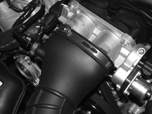
C. Disconnect the mass air flow (MAF) sensor plug and remove the inlet duct and upper air filter cover from the car if applicable. (See Figs. 1-a, 1-b, 1-c.)
Fig. 1-b
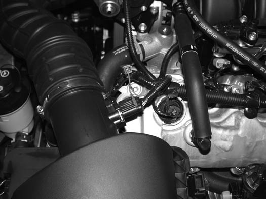
D1. Remove the 10mm headed bolt (located next to the inner fender) which secures the lower portion of the air filter enclosure. Remove the lower portion from the car - it will not be reused. (See Fig. 1-d.)
Fig. 1-c
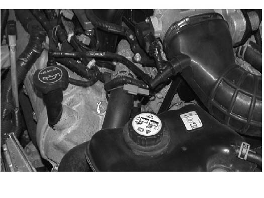
D2. (Bullitt Only) Remove silver nut washer securing the front of the intake shroud. (see Fig 1-d1.)
Fig 1-d
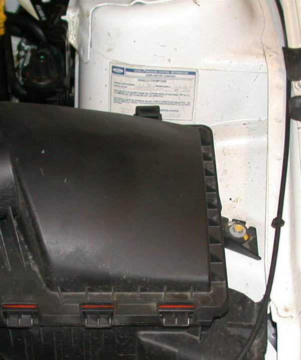
E. Remove the six plastic push pins securing the radiator cover. Remove the cover and set aside to be reinstalled later. (See Fig. 1-e.)
Fig. 1-d1 (Bullitt Only)
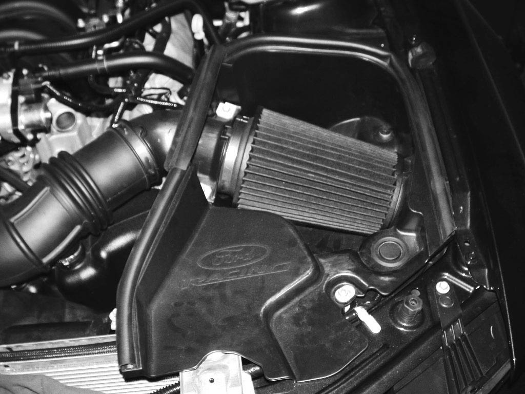
1. PREPARATION/REMOVAL, cont’d
F. Locate the coolant drain plug on the passenger’s side of the radiator. Next drain the coolant into a clean container. This coolant will be reused in a later step.
NOTE: Loosening the coolant reservoir cap will allow for coolant to drain more freely.
Fig. 1-e
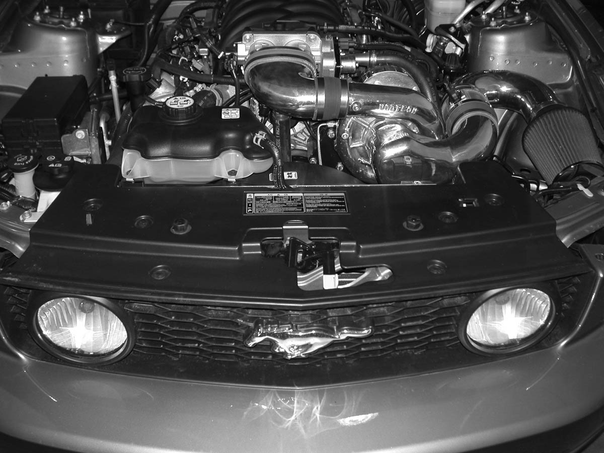
G. Remove the two 8mm headed bolts securing the coolant overflow reservoir to the plastic fan shroud. (See Fig. 1-f.)
H. Disconnect the small overflow hose (running across the top of the radiator) from the overflow reservoir. (See Fig. 1-f.)
Fig. 1-f
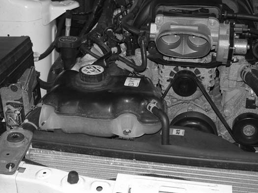
I.1 (2007-2010 Models and Bullitt Only) Remove the large hose connected to the bottom of the coolant overflow reservoir. (See Fig. 1-g.)
I.2 (2005-2006 Only) Remove the large hose connecting the thermostat housing to the bottom of the overflow reservoir. Set the hose and reservoir aside to be reinstalled in a later step. (See Fig. 1-g.)
NOTE: If you are installing H.O. (charge cooled) kit, the coolant reservoir will not be reused. Retain only the fill cap for reuse.
Fig. 1-g
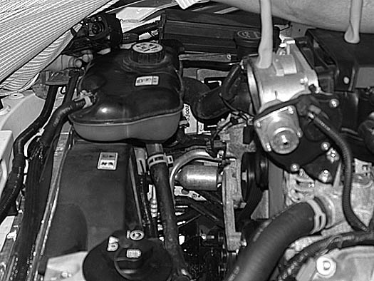
J.1. (2005-2006 Only) Remove the two upper radiator hoses from the engine coolant crossover tube and set aside. The radiator hose located on the driver’s side will not be reused. (See Fig. 1-g.)
J.2. (2007-2010 Only) Remove single upper radiator hose. This host will be reused in a later step.
K. (2005-2006 Only) Remove the thermostat housing from the large formed hose leading to the engine block and the lower outlet of the radiator. (See Fig. 1-h.) Set the thermostat housing aside to be reinstalled in a later step.
L. (2005-2006 Only) Remove the lower hose on the radiator and set the hose aside, as it will not be reused.
M. Drain and remove the power steering reservoir. This reservoir will be relocated in a later step.
N.1 Disconnect and remove the factory 5/8" plastic breather hose assembly attached to the driver’s side valve cover and intake manifold. Remove the two fittings from the ends of the plastic tube for re-use. Discard the striped plastic tube. (See Fig. 1-i.)
N.2 (Bullitt Only) Remove strut tower brace two nuts each side with a 13mm socket.
1. PREPARATION/REMOVAL, cont’d
O. The installation of this supercharger system requires the removal, in part or whole, of the intake manifold so that modifications can be made to the coolant crossover tube or thermostat housing depending on year of application:
1. (2005-2006 Only) Unplug the wire connectors from each of the eight injectors. Remove all of the vacuum hoses and connectors located at the front and rear of the intake manifold. Remove the connector attached to the intake manifold runner control (IMRC) unit located at the rear of the manifold on the passeger’s side.
Fig. 1-h
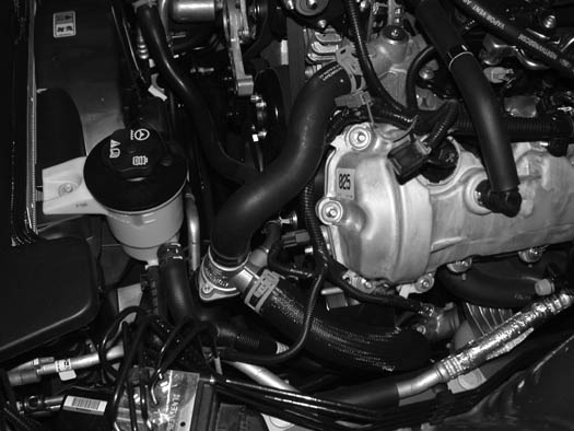
2. (2007-2010 Only): Unplug the wire connectors from each of the eight injectors.
3. Remove the four 8mm headed bolts securing the injector rails to the intake manifold. Do not remove the small clips that retain the injectors to the fuel rails. Using a 5/8" spring lock tool, disconnect the fuel feed line from the fuel rail. Remove the vacuum line from the fuel regulator. Remove the rails and injectors as a complete unit and set aside. New injectors will be installed in a later step. (See Figs. 1-i, 1-j.)
Fig. 1-i
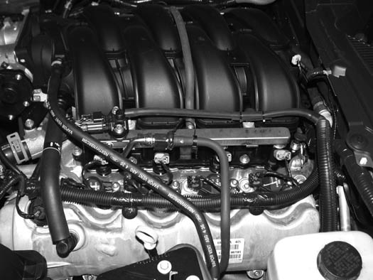
4. Locate and remove the remaining 10mm headed bolts retaining the intake manifold to the cylinder heads. There are five on each side.
5. (2005-2006 Only): Remove the intake manifold and set aside so it can be reinstalled after modifications to the coolant crossover tube are made.
Fig. 1-j
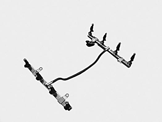
NOTE: Modification to the crossover tube will be completed in a later step
6. (2007-2010 Only): It is not necessary to remove the intake manifold from the vehicle completely. Raise the front of the manifold 3-4" and support between the throttle-body and alternator.
NOTE: Modification to the thermostat will be completed in a later step.
1. PREPARATION/REMOVAL, cont’d
P. Using a 1/2" ratchet, release the tension from the accessory drive belt and remove it from the car. This drive belt will be replaced with a longer one later in the installation.
Q. Locate and remove the stud bolt that secures the alternator in place as well as the bolt located to the right of the alternator. (See Fig. 1-o.) Using a 15mm socket or wrench, remove the nut that secures the capacitor, resistor and coolant hose support bracket to the stud bolt. Using an 18mm socket or wrench, remove the stud bolt, it will be modified and replaced in a later step.On 2010 Models, no coolant hose support bracket is used.
Fig. 1-o
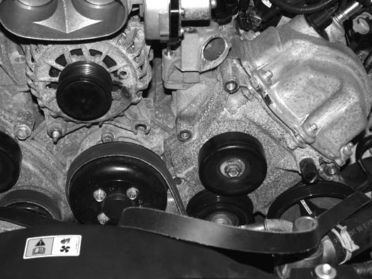
R. There is a small tab that secures the wiring harness in place on the valve cover that will need to be removed to gain clearance for the supercharger belt. This tab is best removed with a small air saw but a grinder will work. After removal, smooth the area to prevent damage to the belt. (See Figs. 1-r, 1-r1.)
Fig. 1-r
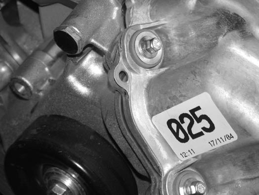
S. As seen in Fig. 1-o, the upper bolt is removed from the timing chain cover. This bolt will have to be modified by cutting off the threaded end where the resistor attaches. Modify and reinstall the bolt. (See Fig. 1-s.)
Fig. 1-r1
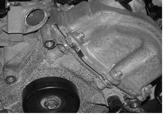
T. Disconnect the plug to the cam position sensor. Remove the wiring harness from the retaining clips that hold it to the valve cover. Move the harness out of the way. This harness will have to be relocated to gain clearance for the supercharger.
Fig. 1-s
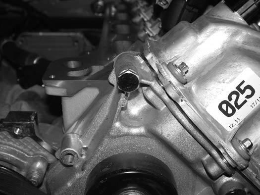
2. OIL FEED INSTALLATION (Engine oil-fed kits only. Applications with V-3 superchargers skip
A. Locate the factory oil sensor on the driver’s side of the vehicle near the oil filter.
B. Remove the sending unit and set aside.
C. Locate the supplied 1/4"NPT street TEE fitting. Install the TEE in the same location as the factory sending unit with the 1/4" x –4 x 90° installed on the TEE at the location noted. (See Fig. 2-a.)
D. Attach the stainless steel –4 hose to the –4 fitting installed in the street TEE. (See Fig. 2-a.)
E. Route the hose away from hot, sharp or moving parts and move to the top of the engine where it will be attached to the supercharger oil feed.
F. Reinstall the factory sensor in the branch of the TEE as shown. (See Fig. 2-a.)
NOTE: The oil feed hose to the S/C will be installed in a later step of the installation. Temporarily cap the open end of the hose to prevent contamination to the inside of the hose.
Fig. 2-a
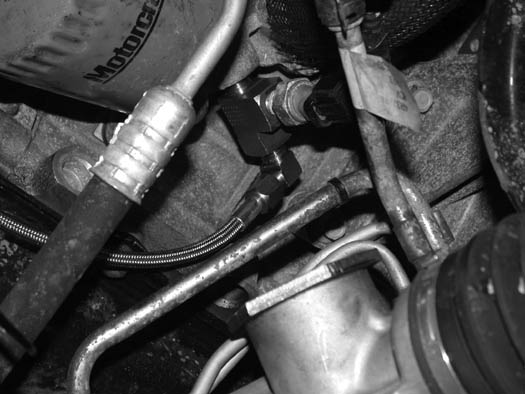
3. OIL DRAIN ASSEMBLY INSTALLATION (Engine oil-fed kits only. Applications with V-3 supercha
A. To provide an oil drain for the supercharger, it is necessary to make a hole in the oil pan. It is best to punch the hole rather than to drill it.
B. Remove paint from the area around the hole.
C. Mark the oil pan 5/8" down from the oil pan mounting rail on the driver’s side of the engine. Measure forward 3/4" from the first bolt on the side of the oil pan. (See Fig. 3-a.)
Fig. 3-a
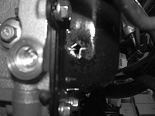
D. Use a small center punch to perforate the pan and expand the hole. Switch to a larger diameter punch and expand the hole further to approximately Ø9/16". Most punches are made from hexagon material and may be placed in a socket with an extension to make this procedure easier.
E. Tap the hole with a 3/8"NPT tap approximately 1/4" deep. Pack the flutes of the tap with heavy grease to hold chips. Use a small magnet to check for any stray chips.
NOTE: This method of rolling over the lip of the hole and tapping it works very well if carefully done and should cause no problems
F. Thoroughly clean the threaded area. Apply a small amount of silicone sealer or teflon paste to the new threads. Apply more sealer to the 3/8"NPT hose fitting and secure in the hole. Make sure a seal is formed all around the fitting. (See Fig. 3-b.)
G. Drain the engine oil and change the filter.
Fig. 3-b
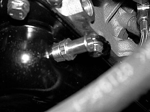
4. POWER STEERING RELOCATION (2010 Models Skip to Step 4.1)
A. Locate the power steering assembly 4FU110-010.
B. Attach the power steering (P/S) relocation bracket 4FU010-010 with the hardware provided to the P/S reservoir removed in an earlier section. (See Fig.4-a.)
C. Attach the 3/4" P/S hose along with the 3/8" P/S hose to the outlets of the reservoir with the clamps provided. (See Fig. 4-b.)
Fig. 4-a
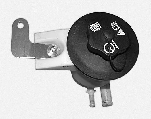
D. Attach the 3/4" and the 3/8" hose barb unions to the factory hoses using the factory clamps.
E. Attach the reservoir to the passenger’s side radiator core support using one of the factory ground strap retaining bolts. (See Fig. 4-c.)
Fig. 4-b
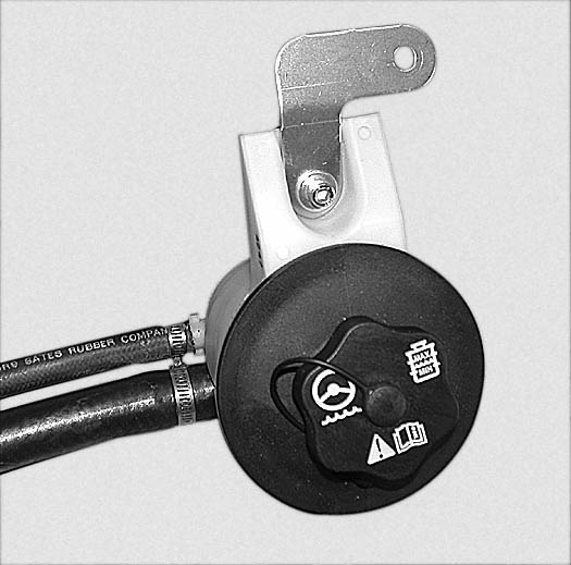
F. Attach the hoses from the reservoir to the factory P/S hoses and secure with the supplied clamps. Trim for best fit. Secure the hose to the fan shroud away from heat and moving objects.
Fig. 4-c
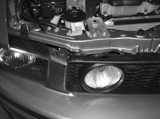
G. It will be necessary to trim the corner of the radiator core support cover to clear the relocated P/S reservoir. (See Fig. 4-d)
Fig. 4-d
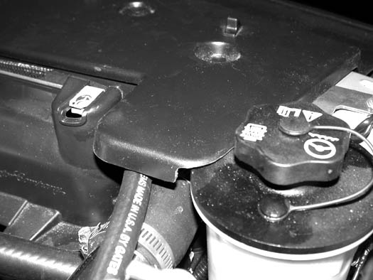
4.1 POWER STEERING RELOCATION (2010 Models Only)
A. Locate the power steering assembly 4FU110-010.
B. Attach the power steering (P/S) relocation bracket P/N 4FU010-101 (R) with the hardware provided to the P/S reservoir removed in an earlier section.
C. Locate the factory 3/4" PS hose and cut off the 90º bend as shown. See fig 4.1a.
Fig. 4.1a
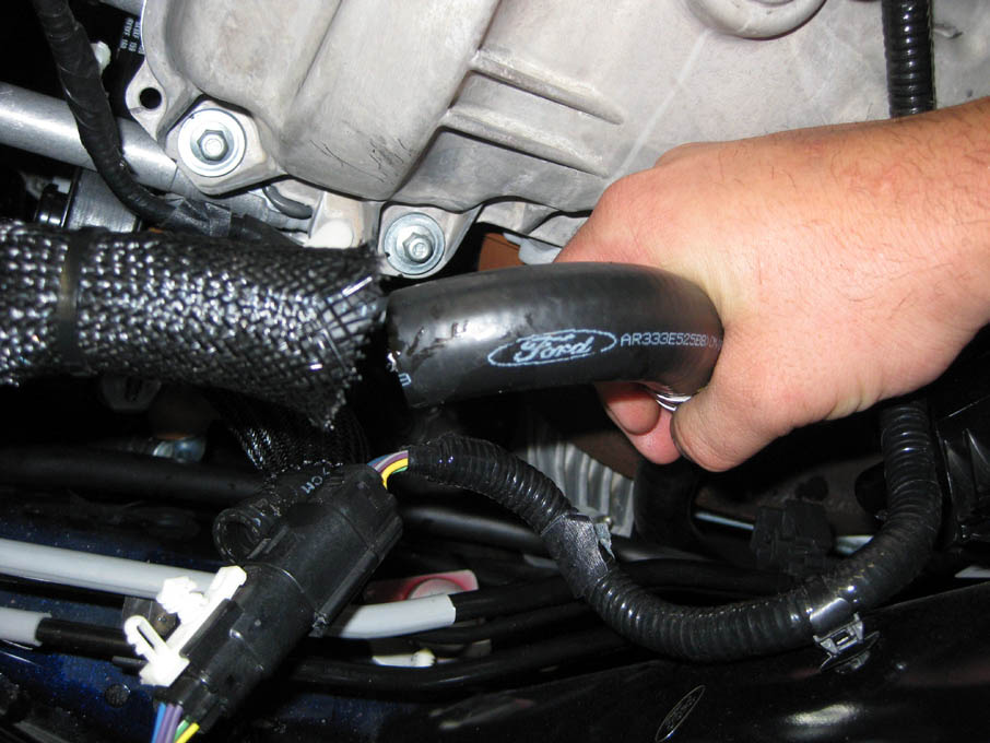
D. Using a 3/4" brass union and two stepless clamps, attach the 90º bend to a length of supp
Fig. 4.1b
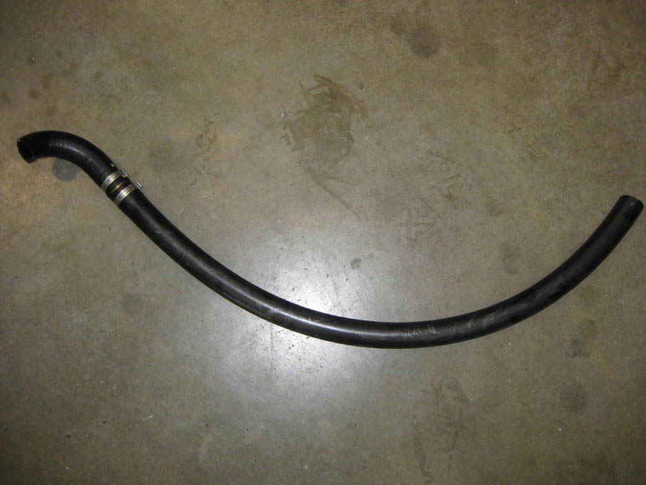
E. Attach 90º 3/4" and a length of supplied 3/8” hose to reservoir using the factory clamps. Remove the inboard 13mm headed strut mount nuts and install PS reservoir assembly in location shown. See fig 4.1c.
Fig. 4.1d
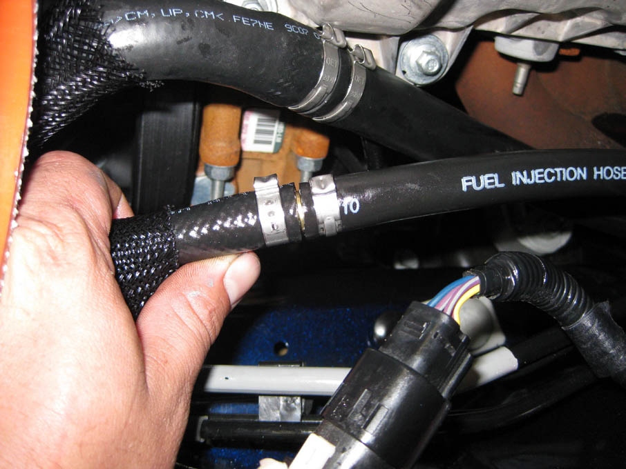
F. Route hoses towards front of vehicle away from exhaust and moving objects. G. Connect pre
Fig. 4.1c
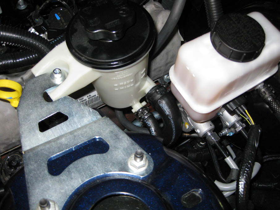
5.1 COOLANT TUBE RELOCATION (2005-2006 Models Years Only)
NOTE: For 2007-2010 Models skip to Section 5.2.
A. Locate assembly 4FU214-021.
B. Remove the hose connected to the back, lower portion of the engine coolant crossover tube. (See Fig. 5.1-a.)
Fig. 5.1-a
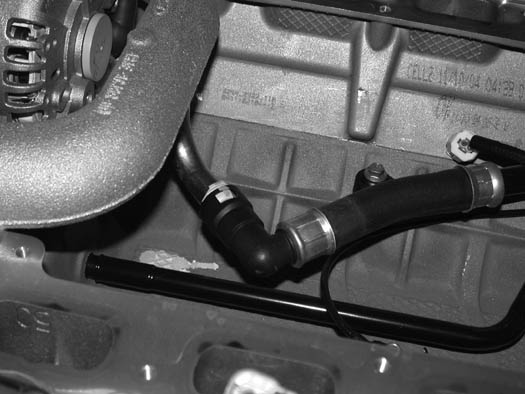
C. Remove the nylon clip retaining the wire harness to the alternator brace and the four 10mm headed bolts securing the alternator brace. Set the brace aside to be reinstalled. (See Fig. 5.1-b.)
Fig. 5.1-b
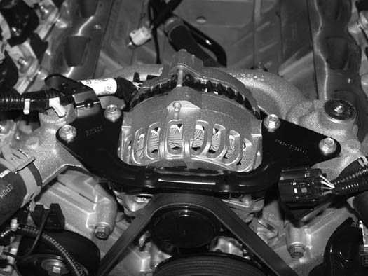
D. Remove the factory coolant bleed plug and set the plug aside. It will not be reused. (See Fig. 5.1-c.)
E. Remove the remaining two 10mm head bolts securing the crossover tube to the cylinder heads.
Fig. 5.1-c
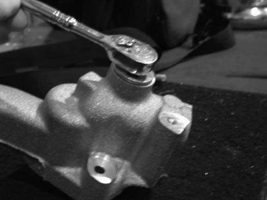
5.1 COOLANT TUBE RELOCATION (2005-2006 Models Years Only), cont’d
F. Remove the factory O-ring type gaskets to prevent damage from heat. Clamp the steel hose barb end of the coolant crossover tube in a vise as shown. Using a small amount of heat, heat the aluminum crossover tube. Using a twisting motion, remove the steel insert. (See Fig. 5.1-d.) Penetrating oil will also aid in this step.
Fig. 5.1-d
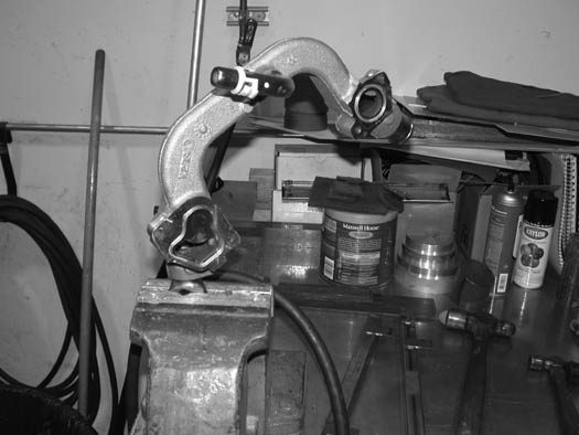
G. Locate the supplied 1-1/4" expansion plug (7P125-002).
H. Coat the expansion plug with sealant. Using a tube or socket that matches the recessed diameter of the plug, install the plug flush with the machined surface sealing the outlet of the crossover tube. (See Figs. 5.1-e, 5.1-f.)
Fig. 5.1-e
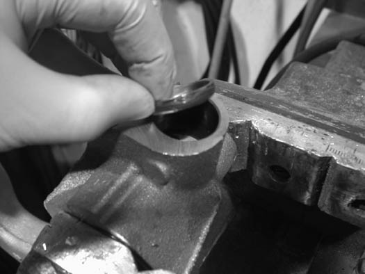
Fig. 5.1-f
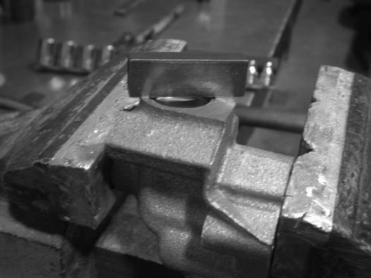
I. Locate the supplied coolant relocation fitting, sealing nut and O-ring washer. (See Fig. 5.1-g.)
Fig. 5.1-g
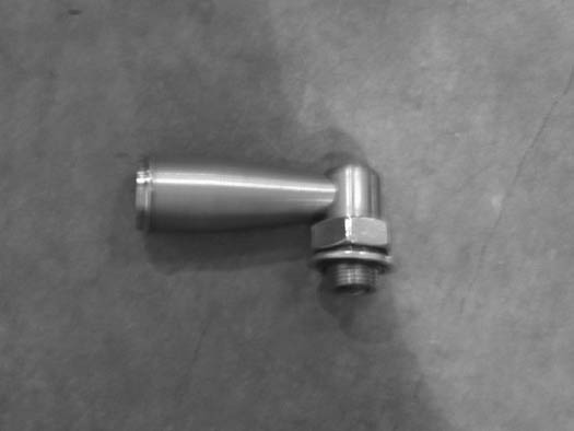
J. Install the fitting in the location of the factory coolant bleed plug. (See Fig. 5.1-h.) Screw the jam nut all the way onto the fitting. Tighten the fitting in the position shown. (See Fig. 5.1-h.) Secure with the jam nut.
NOTE: It is recommended that sealant be used to seal the thread of the fitting.
Fig. 5.1-h
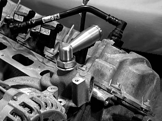
K. Reinstall the factory O-ring gaskets to the crossover tube.
L. Set the coolant crossover tube back in its original location.
M. Reinstall the two 10mm headed bolts through the crossover tube into the cylinder heads. Temporarily install two intake manifold retaining bolts through the crossover tube into the cylinder heads, where the manifold will be secured. Leave these loose as they are there only as a pilot for the crossover tube.
N. Tighten the crossover tube retaining bolts, and remove the two manifold retaining bolts.
O. Reconnect the coolant crossover tube hose at the lower rear portion of the coolant crossover tube. Remove any coolant that may have spilled into the engine valley.
P. Reinstall the alternator support bracket and the four 10mm headed retaining bolts removed earlier. Attach the capacitor resistor removed from the stud bolt on the front cover to one of the 10mm bracket retainers. Route the resistor and its wire away from moving parts.
NOTE: Leave two 10mm headed bolts that attach the bracket to the crossover tube loose.
Q. Reinstall the Intake Manifold removed in a previous step. Check to see that the rubber intake runner gaskets are in place and undamaged. Make sure the cylinder head surface is clean.
R. Lower the intake manifold onto the cylinder heads.
S. Install the ten factory 10mm headed manifold retainers and tighten to factory specifications. Tighten the two 10mm headed bracket bolts that were previously left loose.
T. Reconnect the IMRC control unit at the rear of the manifold along with the vacuum hose.
U. Remove the small clips that retain the factory fuel injectors to the fuel rail. Remove the factory fuel injectors and set aside - they will not be reused.
V. Locate the supplied fuel injectors. Lubricate the injector O-rings with clean motor oil and install into the fuel rail. Reinstall the small retaining clips onto the injectors.
W. Lower the fuel rail/injector assembly onto the manifold, making sure that the injectors seat properly into the manifold. Secure with the four factory 8mm headed bolts.
X. Reconnect the fuel injector plugs and all other connections and vacuum lines previously removed from the manifold assembly.
5.2 THERMOSTAT HOUSING/RADIATOR HOSE MODIFICATION (2007-2010 Model Year Only)
A. Using an 8mm socket, remove the two 6mm screws that retain the thermostat housing. Set the housing aside to be reused later. Leave the factory thermostat and O-ring seal in place as they will be reused (provided they are in good condition). (See Fig. 5.2-a.)
Fig. 5.2-a
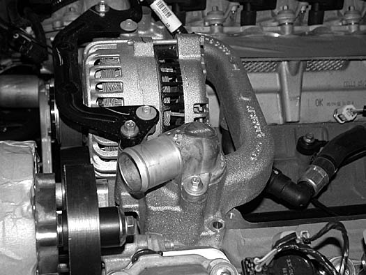
B. Locate the supplied thermostat housing adaptor and hardware. Using the two 6mm socket-head screws, install the housing adaptor as shown. (See Fig. 5.2-b.)
Fig. 5.2-b
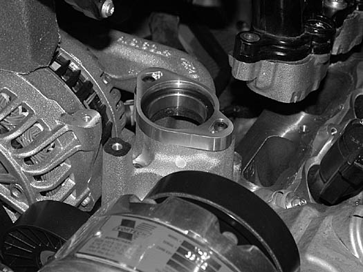
C. Using the 6mm hardware, washers and O-ring provided, reinstall the thermostat housing. Attach the previously removed resistor to the housing as shown. (See Fig. 5.2-c.)
Fig. 5.2-c
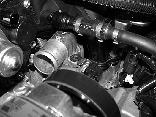
D. Reinstall the intake manifold removed in a previous step. Check to see that the rubber intake runner gaskets are in place and undamaged. Make sure the cylinder head surface is clean.
E. Lower the intake manifold onto the cylinder heads.
F. Install the ten factory 10mm headed manifold retainers, and tighten to factory specifications.
G. Remove the small clips that retain the factory fuel injectors to the fuel rail. Remove the factory fuel injectors and set aside. These will not be reused.
H. Locate the supplied fuel injectors. Lubricate the injector O-rings with clean motor oil and install into the fuel rail. Reinstall the small retaining clips onto the injectors.
I. Lower the fuel rail/injector assembly onto the manifold, making sure that the injectors seat properly into the manifold. Secure with the four factory 8mm headed bolts.
J. Reconnect the fuel injector plugs, all other connections and vacuum lines previously removed from the manifold assembly.
K. Locate the 4FU114-030 water pipe assembly.
L. Cut approximately 2.25" off the short 90° end of the factory radiator hose and set aside. (See Fig. 5.2-l.)
M. Cut the remainder of the short 90° bend from the factory radiator hose, approximately half way between the 90° bend and the 45° bend, and discard. (See Fig. 5.2-l.)
Fig. 5.2-l
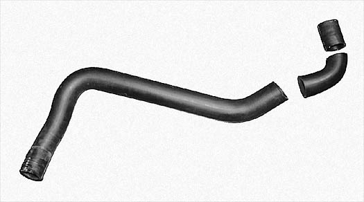
N. Using the 2.25" section of radiator hose cut previously and two #24 hose clamps provided, install the short end of the 90° stainless tube (4FU014-060) onto the repositioned thermostat housing. (See Fig. 5.2-n.)
Fig. 5.2-n
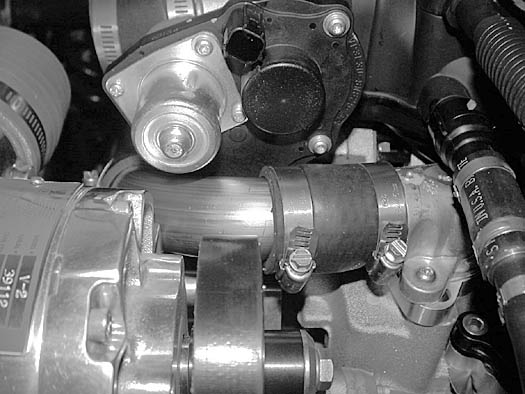
O. Slide the protective sleeve provided over the modified hose. Install the remainder of the factory radiator hose using one factory hose clamp and one #24 hose clamp. (See Fig. 5.2-o.)
Fig. 5.2-o
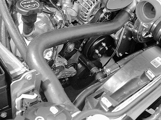
6.1 PULLEY AND SPACER REPLACEMENT (Bullitt/V-Power/8-Rib Kits Only - All others skip to step
A. Unplug the cam sensor connector.
B. Tensioner modification (skip to step c. if installing belt tensioner assist):
1. Remove the three screws retaining the factory spring tensioner to the front of the engine. Remove the factory steel idler from the tensioner and replace with the supplied 3" idler (4FU116-031) using the factory hardware. (See Fig. 6.1-a.)
2. Install the three M8 x 40mm bolts w/washers through the tensioner mounting holes.
3. Slide the three .75"OD x .328"ID x .140" spacers onto the three bolts protruding through the tensioner. (See Fig. 6.1-a.)
4. Secure the tensioner assembly to the front of the engine. Use Fig. 6.1-a as guide for spacer placement.
Fig. 6.1-a
6.1 PULLEY AND SPACER REPLACEMENT (Bullitt/V-Power/8-Rib Kits Only - All others skip to step
C. OPTIONAL Belt tensioner assist up-grade:
1. Remove the three screws retaining the factory spring tensioner to the front of the engine. Remove the factory steel idler from the tensioner and replace with the supplied 3" idler (4FU116-031) using the factory hardware. (See Fig. 6.1-C1.)
Fig. 6.1-C1 (optional)
2. Locate the supplied tensioner assist plate. Install the supplied 3/8-16 x 2.5" screw and 3/8-16 jam nut into the plate. Install the three M8 x 55mm bolts w/washers through the plate. Slide the three .75"OD x .328"ID x .927" long spacers onto the previously installed hardware. (See Fig. 6.1-C2.)
See Fig. 6.1-C2 (optional)
3. Install the plate, hardware and spacers onto the factory spring tensioner. Slide the three .75"OD x .328"ID x .140" spacers onto the three bolts protruding through the tensioner. (See Fig. 6.1-C2.)
4. Secure the tensioner assembly to the front of the engine. Use Figs. 6.1-C1, 6.1-C2 as guides for spacer placement.
NOTE: Leave the 3/8" screw and jam nut loose at this time.
D. Remove the factory idler pulley located just above the spring tensioner location. Replace with the supplied 3.5" idler (4FU016-021) and .875"OD x .663"ID x .101" thick spacer (2A017-882-02) using the factory hardware. (See Fig. 6.1-a.)
E. Replace the alternator pulley:
1. First remove the plastic cap from the end of the alternator pulley to reveal the splined hub.
2. Rotate the pulley so that a round punch can be inserted through the front of the alternator into the alternator-cooling fan. This will hold the alternator assembly from turning. Using the appropriate splined hub tool (see notes on page iv), loosen and remove the alternator pulley. The threads are standard.
3. Install the supplied 8-rib alternator pulley (4FU016-011) and secure using the M16 x 1.50" flanged nut provided.
F. Remove the two bolts that retain the factory idlers to the front cover. Discard the idlers and bolts. Replace the top idler with the 3.5" smooth idler (4FU016-021) .875"OD x .663"ID x .101" spacer and stud bolt provided. Replace the lower idler with the 3.5" ribbed idler (4FU016-041) .875"OD x .663"ID x .101" spacer and stud bolt provided. (See Fig. 6.1-c.)
Fig. 6.1-c
G. Using the appropriate pulley puller, remove the factory power steering pulley and discard. Replace with the supplied 8-rib power steering pulley with the appropriate installer tool.
H. Remove the A/C clutch retaining screws. Carefully remove the clutch and set aside with the hardware and small spacer located between tip of A/C compressor drive shaft and A/C clutch spline. Replace with the supplied 8-rib A/C pulley (4FR016-021), and secure using the factory hardware and spacer.
I. Remove the crank pulley retaining bolt. Using the appropriate pulley puller, remove the crank pulley and discard. Install the supplied 8-rib crank pulley using the factory retaining bolt. (Thread locking compound must be applied to the screw threads.)
J. Loosely install the 8-rib drive belt provided using Fig. 6.1-c for belt route reference. Not all pulleys are installed at this time.
NOTE: See Fig. 6.1-d for the next few steps.
K. S/C mounting plate installation:
1. Install the two 140mm bolts into their mounting plate hole locations and slide the two 2.691" long spacers onto them. (See Figs. 6.1-d, 6.2-a.)
Fig. 6.1-d
2. Install the idler plate onto the previously installed hardware and spacers.
3. Install the .097" long spacer onto the bolt that will be secured through the alternator. (See Figs. 6.1-d, 6.2-a.)
4. Loosely install the S/C mounting plate assembly using the original S/C mounting plate hardware, taking care to route the drive belt on the correct side of the spacers. (See Figs. 6.2-b, 6.2-c.)
5. Locate the remaining 3.5" smooth idler (4FU017-031), .544" long pilot spacer, and 1.597" long spacer as depicted in Fig. 6.1-d.
6. Install the idler pulley assembly referencing Figs. 6.1-d, 6.2-a.
6.2 SUPERCHARGER MOUNTING PLATE INSTALLATION
A. The mounting plate is provided with the spacers and bolts as they would be installed on the vehicle. Keep these bolts and spacers marked as to their locations. They are all different in size and mismatching them will result is misalignment of the mounting plate.
Fig. 6.2-a 2005-2008 NON-COOLED & 2010 H.O. MODEL IDLER LOCATION
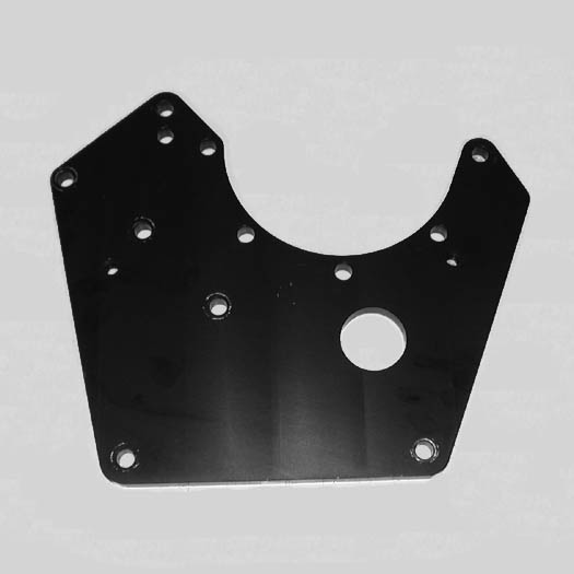
B. (Non V-Power/Bullitt Kits only) Locate the two supplied stud-bolt spacers (see Figs. 6.2-b, 6.2-c) in the S/C mounting plate assembly. Remove the factory screws retaining the idler pulleys on the driver’s side of the engine and replace with the stud spacers.
Fig. 6.2-b NOTE: This figure is just for reference. The small idler pulley mounting bracket
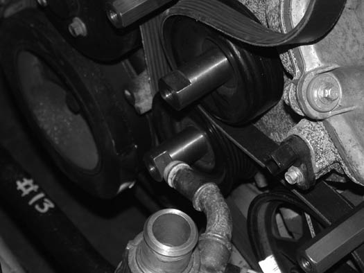
C. It is necessary to install the supercharger accessory drive belt and loosely route it following Fig. 6.2-c, as not all pulleys are currently in place.
Fig. 6.2-c
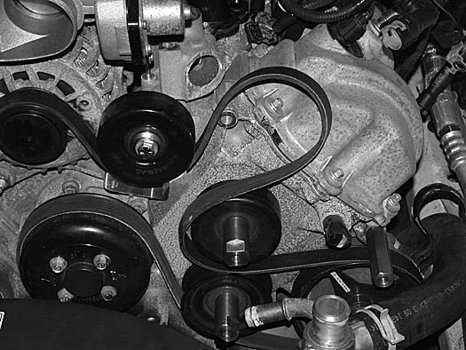
D. Locate the supercharger mounting plate 4FU010-044 from the supercharger mounting plate assembly. (See Fig. 6.2-a.)
E. (Non V-Power/Bullitt Kits only) Locate the two 8mm x 140mm long bolts and washers from the mounting bracket assembly and install in the locations noted. (See Fig. 6.2-a.)
F. Slide the two long spacers onto the bolts previously installed. (See Fig. 6-f.) Install the small triangle-shaped idler pulley mounting bracket to the spacers. Install the .093" spacer onto the bolt that will be attached in the alternator location.
G. Lower the mounting plate assembly into position on the front of the engine. Be sure to route the drive belt on the correct side of the idler bracket and spacers. (See Fig. 6.2-g.)
H. Loosely attach the plate using the previously installed 140mm hardware. Locate the two 3/8-16 x 1.0" bolts and washers and install through the plate into the two stud bolt spacers retaining the factory idlers. (See Figs. 6.2-a, 6.2-c.)
I. Locate the 8mm x 150mm bolt and washer. Loosely install the bolt through the mounting plate and remaining long spacer into the engine cover using Fig. 6.2-a for location reference.
J. (Non V-Power/Bullitt Kits only) Locate the supplied idler, 1.776" idler spacer, idler pilot spacer, 3/8-16 x 3.75" long bolt and washer. Install the bolt/washer through the mounting plate, 1.776" spacer, supplied idler, idler pilot spacer and into the triangle-shaped bracket. (See Figs. 6.2-f to 6.2-h for assistance.)
Fig. 6.2-e / Belt routing
Fig. 6.2-f
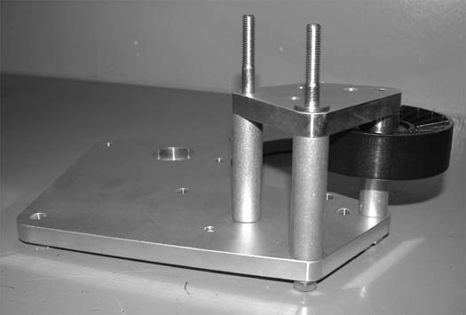
K. Tighten all mounting plate hardware, making sure the drive belt is properly routed and no wiring or hoses are caught between the mounting surfaces. (See Fig. 6.2-g.)
Fig. 6.2-g
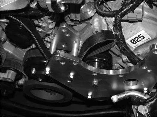
L1. (Non V-Power/Bullitt Kits only) Install the five 3/8-16 x 1.0" bolts and washers through the back side of the mounting plate. (See Fig. 6.2-h.)
Fig. 6.2-h
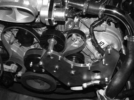
L2. (V-Power/Bullitt Kits only) Install the five 3/8-16 x 1.5" supplied bolts and washers through the back side of the mounting plate. Install the five .280" long spacers (2A017-878-08) onto the previously installed hardware. (See Fig 6.1-d)
*M. Attach the supplied length of 1/2" oil drain line hose, and one #8 hose clamp from the previously installed oil drain assembly, to the 1/2" barbed fitting in the supercharger.
*N. Install the supplied 1/8"NPT x -4 straight fitting from assembly 4FU130-026 to the oil feed fitting on the supercharger.
NOTE: Use only clean engine oil on the pipe threads. Teflon tape or pipe sealant is not recommended as it might loosen and cause blockage of the small oil feed orifice resulting in possible supercharger failure.
O. Attach the supercharger assembly to the mounting plate using the previously installed hardware. A 9/16" ratcheting end wrench will greatly aid in this step.
*P. Secure the oil drain hose to the prevously installed brass fitting in the oil pan, making sure to route in a smooth downward manner and away from moving or hot objects.
NOTE: Any dips, “uphill” sections, kinks or restrictions may cause drainage problems and possible supercharger failure.
*Q. Attach the -4 oil feed hose to the straight -4 fitting previously installed in the supercharger. Secure away from moving or hot objects.
R. Using a 1/2" ratchet, rotate the factory spring tensioner clockwise and install the accessory drive belt. (Refer to Fig. 6.2-e for proper belt routing.)
S. Optional belt tensioner assist upgrade only: Once the drive belt has been installed, snug the tensioner assist bolt. Lock in place with the previously installed jam nut.
NOTE: Do not overtension the tensioner assist bolt, as damage may occur to the OEM tensioner..
T. Reconnect the cam sensor plug.
**U. Secure the remote drain hose away from the belt and other hoses using tie-wraps
* Applies to "engine oil-fed" units only. V-3 applications skip these steps
** Applies to V-3 applications only
7. THERMOSTAT HOUSING RELOCATION (2005-2006 Only)
A. It will be necessary to relocate the thermostat housing to gain clearance for the supercharger mounting bracket.
B. Locate hose 7U133-050. This hose will be modified and replace the factory lower radiator hose removed in a previous step. (See Fig. 7-a.)
Fig. 7-a
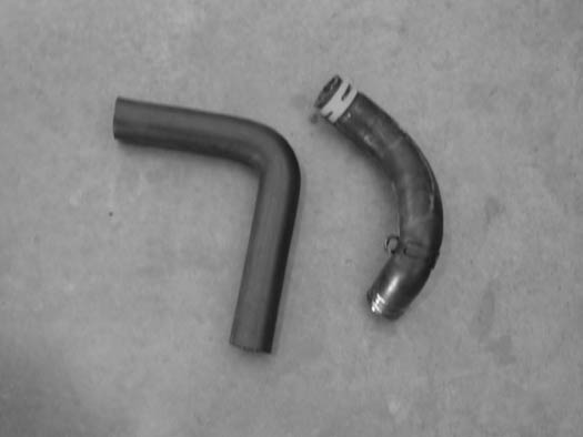
C. Modify the supplied hose as seen in the figures below. (See Figs. 7-b, 7-c.)
Fig 7-b
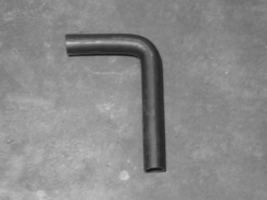
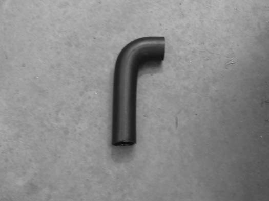
Fig. 7-c
D. Trim approximately 5" off of the 9" end of the hose and 5-1/4" off the 13" end. (See Fig. 7-c.)
NOTE: Because of manufacturing tolerances, it is best to leave this hose long and trim to fit.
E. Install the long end of the modified hose to the outlet of the radiator with a #24 hose clamp. Leave the clamp loose for adjustment.
F. Install the thermostat housing to the open end of the new, lower radiator hose and the large formed factory hose. Adjust the thermostat’s location making sure it clears any moving parts.
NOTE: The hose clamps will be left loose for adjustment of the thermostat’s location until after the installation of the supercharger and supercharger mounting bracket.
G. Locate the 7U133-190 molded coolant hose. (See Fig. 7-c.)
H. Install the end with the 90° bend onto the thermostat housing.
I. Install the opposite end to the previously modified coolant crossover tube. Secure using the #20 hose clamps provided. (See Fig. 7-c.)
Figure 7-d
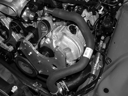
8. CHARGE AIR COOLER INSTALLATION (CHARGE COOLED KITS ONLY)
NOTE: For non-cooled kits skip this section and proceed to Section 9.
A. BUMPER COVER AND SPLASH PAN
1. Raise the vehicle with a floor jack and set on jack stands.
2. Remove the seven 5.5mm headed screws retaining the lower splash panel. (See Fig. 8A-a.)
Fig. 8A-a
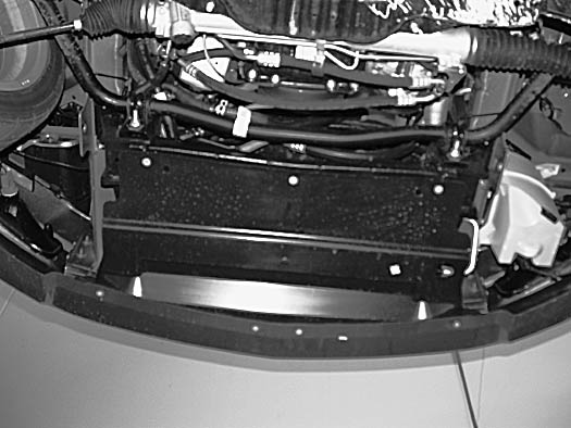
3. Remove the six Phillips-head screws (three on each side) from the lower portions of the plastic innner fender liners. (See Fig. 8A-b.).
On 2010 Models, remove the four 7mm headed screws (2 per side) from the lower portions of the plastic inner fender liner.
Fig. 8A-b
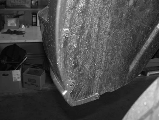
4. Remove the five plastic clips retaining the front portion of the fender liner. Both sides need to be removed. (See Fig. 8A-c.)
Fig. 8A-c
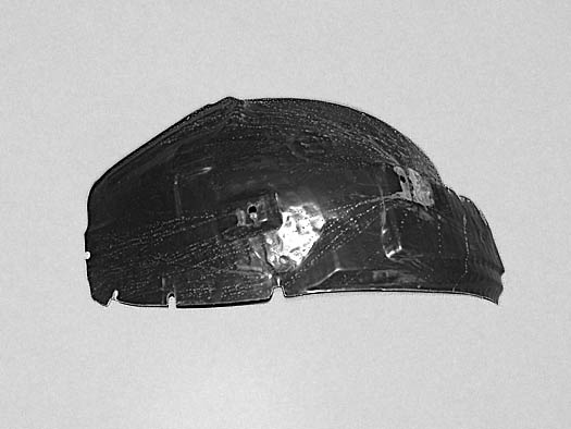
5. Remove the four 10mm nuts (two on each side) retaining the bumper cover to the fenders. (See Fig. 8A-d.)
2010 models do not use the bracket depicted in Fig.8A-d. Pull outward from rear most portion of the bumper where it attaches to the inner fender to unsnap from retainers. The bumper detaches along the bumper to fender body line and underneath the headlights.
Fig. 8A-d
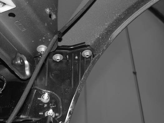
6. Disconnect the connectors on the parking and the lower fog lights. (See Fig. 8A-e.)
Fig. 8A-e
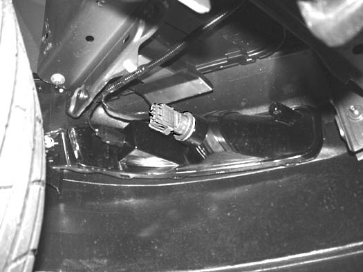
7. Remove the six nylon clips retaining the upper radiator core support cover. (See Fig. 8A-f.)
Fig. 8A-f

8. Remove the two 10mm headed bolts (one on each side in the upper portion of the grill). (See Fig. 8A-g.)
Fig. 8A-g
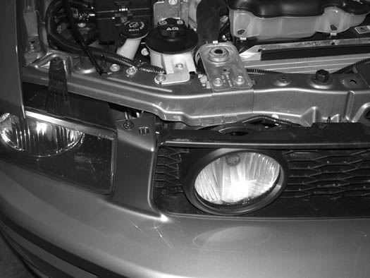
9. Lift up on the tabs releasing them from the clips. (See Fig. 8A-h.)
Fig. 8A-h
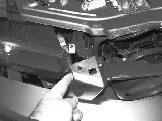
10. Pull out on the bumper cover
11. Remove the connector to the driving light in the grill (if equipped).
12. Remove the bumper cover and set aside. (See Fig. 8A-i.)
Fig. 8A-i
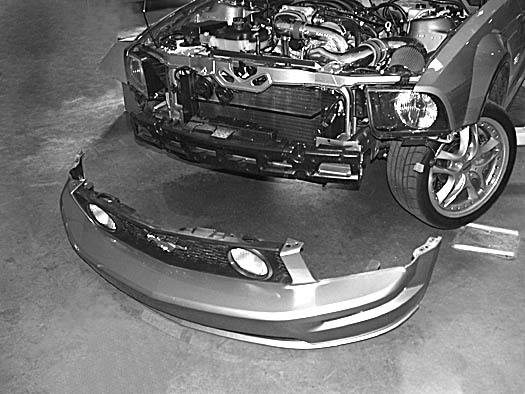
B. WATER COOLER ASSEMBLY INSTALLATION
NOTE: Refer to Fig. 8B-q throughout the following steps:
1. Locate the water cooler assembly 8N106-135.
2. Install the two mounting bracket 8N010-171 and 8N010-173 to the water cooler using the supplied 1/4-20 x 1/2" screws, washers. (See Fig. 8B-a.)
NOTE: Leave these screws loose for adjustment when attaching the assembly to the vehicle.
Fig. 8B-a
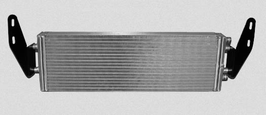
3. Remove four nylon push pins from the styrofoam bumper support and set the support and the pins aside to be reinstalled. (See Fig. 8B-b.)
Fig. 8B-b
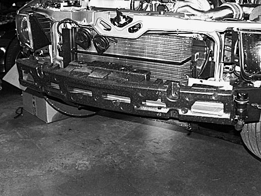
4. Remove six of the eight 13mm headed inset bolts retaining the metal bumper support. (See Fig. 8B-c.)
Fig. 8B-c
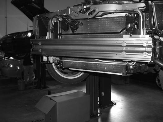
5. 2005-2009 models: Replace the bolts previously removed with the six 8mm x 1.25" x 35mm long bolts and washers provided.2010 models: install four M8x1.25x75mm studs into the four inner bumper bolt holes.
6. 2005-2009 models: Install the four 2A017-036 spacers (two each side) onto the bolts that will secure the water cooler. (See Fig. 8B-d.)2010 models: use four 2A017-753-02 spacers (slightly longer than those depicted in Fig. 8B-d) four 5/16" fender washers, and four nylock nuts
Fig. 8B-d
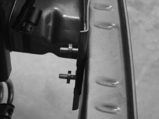
7. Attach the previously assembled water cooler to the bolts and spacers and secure with the 8mm nuts and washers provided. Tighten all cooler hardware at this time. (See Fig. 8B-e.)
NOTE: When installing the cooler, make sure that the water ports are configured as shown in Figs. 8B-a, 8B-q. The “top cooler port” must be the highest point on the cooler for proper air purging.
Fig. 8B-e
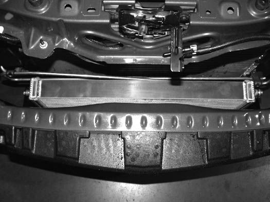
8. Attach the supplied short 90° hose (7U030-065) to the top port on the CAC cooler as shown. (See Fig. 8B-f.)
9. Install one of the supplied 3/4" hose unions into the open end of the previously installed 90° hose and secure. (See Figs. 8B-f, 8B-q.)
Fig. 8B-f
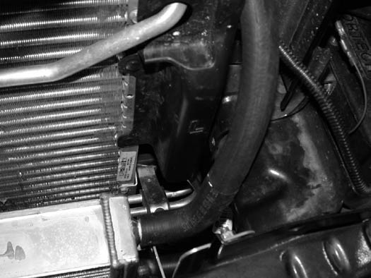
10. 2005-2009 models: Locate assembly 8N104-125. Confirm that the assembly is complete.2010 Models: use assembly 8N104-127
11. Attach the provided ring terminal to the ground wire on the suplied water pump plug harness. Connect the supplied length of 16GA wire to the positive wire using the supplied butt connector. Connect the water pump harness to the water pump.
12. Locate the supplied water pump (8F001-403), two 2-3/8" adel clamps, and water pump mounting bracket. Place the adel clamps on the water pump. Using the supplied 1/4-20 hardware, secure the water pump and clamps to the mounting bracket. When installing, attach the water pump ground wire to one of the water pump mounting clamps using the previously installed ring terminal. (See Fig. 8B-g.)
Fig. 8B-g
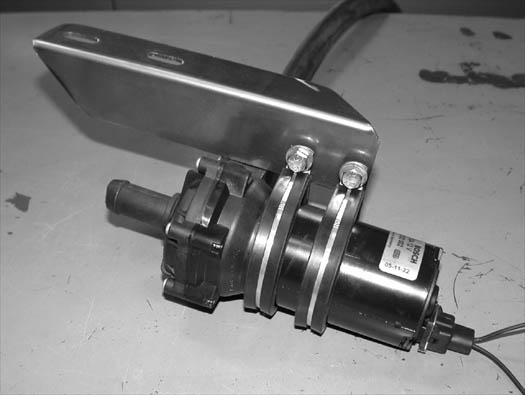
2010 Models: use water pump bracket depicted in Fig. 8B-g2.
Fig. 8B-g2 (2010 Models)
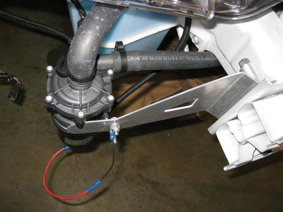
13. Attach the pump assembly to the two 8mm x 35mm long bolts previously installed and secure using the 8mm nuts and washers provided. (See Fig. 8B-h.)
Fig. 8B-h2 (2010 Models)
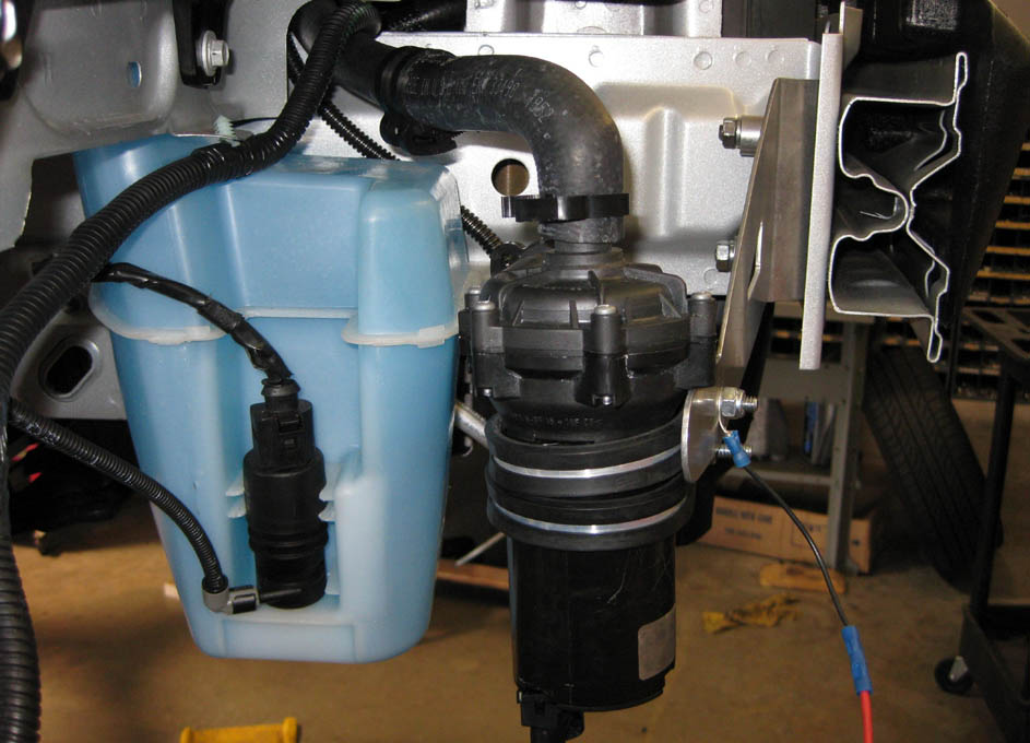
2010 Models: see Fig. 8B-h2
Fig. 8B-h (2005-2009 Models)
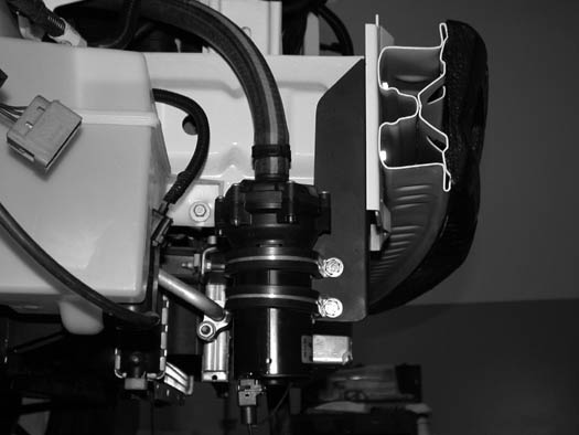
14. Route the positive wire up towards the driver’s side valve cover.
15. Locate the ballast resistor plug. Install the supplied T-tap connector, cut the water pump positive wire (from the water pump) for best fit, attach the supplied male spayed connector and attach to the wire T-tap connnector. (See Fig., 8B-i.)
16. Cut the water pump positive wire and install the inline fuse holder and fuse. Install the wire loom provided and secure away from heat and moving parts. (See Fig. 8B-i.)
Fig. 8B-i
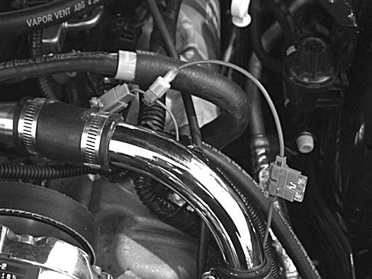
17. Locate the 3/4" x 150° molded rubber hose (7U038-150). Connect the short end of the 3/4" x 150° hose to the lower port on the previously installed water cooler. Install one of the provided 3/4" hose unions into the open end of the 150° hose. Attach a length of 3/4" hose approximately 24" between tthe hose union and the previously installed water pump discharge. Secure all hose connections using the nylon ratchet clamps provided. (See Fig. 8B-j.)
Fig. 8B-j | Viewed From Below
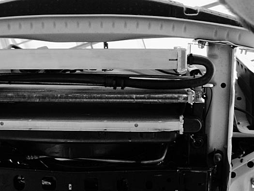
2010 models will require the passenger side air diverter to be trimmed where the power steering cooler line passes through. Enlarge the bottom of this notch 1-1/2˝ for 3/4˝ hose to pass through
18. Attach a length of 3/4" hose approximatelly 48" long to the previously installed water pump feed port and secure. Route the open end of the installed hose toward the passenger’s side shock tower. This hose will be connnected in later step. (See Fig. 8B-h.)
NOTE: The installation of this hose section should maintain an “uphill” routing wthout dips or kinks.
19. Assemble the surge tank reservoir 8N056-060 install a 1/2"NPT x 3/4" straight barbed fitting in the bottom of the surge tank and one 1/2"NPT x 3/4" x 90° in the side. (See Fig. 8B-k.)
Fig. 8B-k
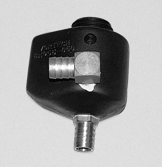
20. Locate and attach the surge tank mounting bracket 8N010-160. Attach the bracket with two 1/4-20 x 1/2" socket head cap screws and washers. (See Fig. 8B-l.)
Fig. 8B-l
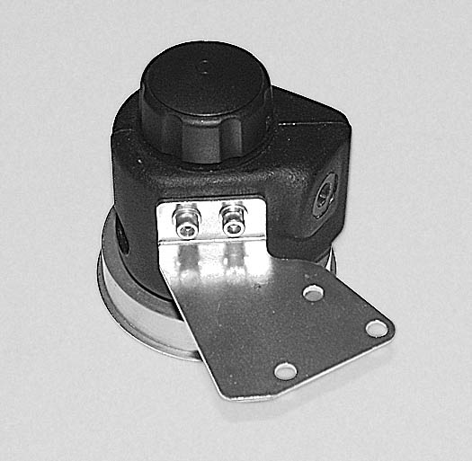
21. On the passenger’s side of the engine, attached to the valve cover, is a large wire harness. The harness will have to be relocated to gain clearance for the surge tank and the radiator overflow reservoir. (See Figs. 8B-n, 8B-m.)
Fig. 8B-m
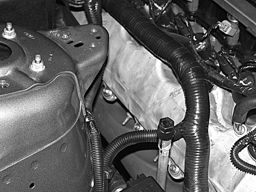
22. Detach the wiring harness from the retaining clips and move the harness to the shock tower. Secure the harness to the A/C line with wire ties. (See Fig. 8B-n.)
Fig. 8B-n
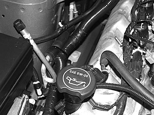
23. Remove the small clip retaining the small wiring harness to the shock tower. (See Fig. 8B-n.)
24. Attach the small harness to the large harness with wire ties.
25. To gain clearance for the coolant reservoir, the A/C line will need to be bent slightly towards the passenger’s side fender. (See Fig. 8B-n.)
NOTE: A/C line is under high pressure. Use caution not to kink or damage the line.
(2005-2006 Only)
26. Remove the 10mm headed screw retaining the ground strap to the bracket on the strut tower. (See Fig. 8B-o.)
Fig. 8B-o
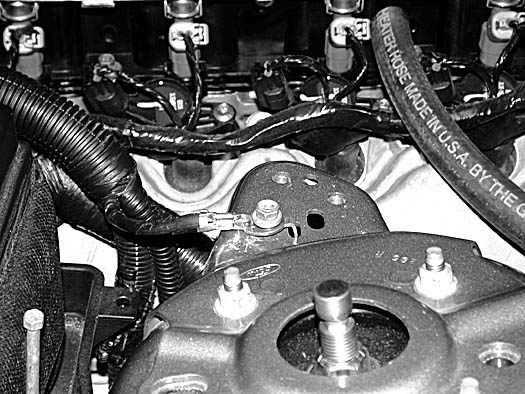
27. Attach the 3/4" hose previously installed to the straight 1/2"NPT x 3/4" barb at the bottom of the surge tank reservoir. Secure with a nylon clamp. (See Fig. 8C-p.)
Fig. 8B-p
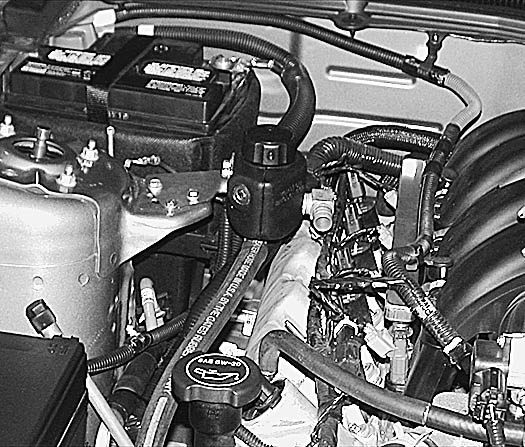
Fig. 8B-q
C. ENGINE COOLANT RESERVOIR INSTALLATION (2005-2006 Models Only)
NOTE: For 2007-2010 models skip to Section 8.E.
1. Locate assembly 8N155-080.
2. Attach the rear reservoir mounting bracket 4FU010-051 to the reservoir with the 1/4-20 x 1/2" long bolts and washers provided. (See Fig. 8C-a.)
Fig. 8C-a
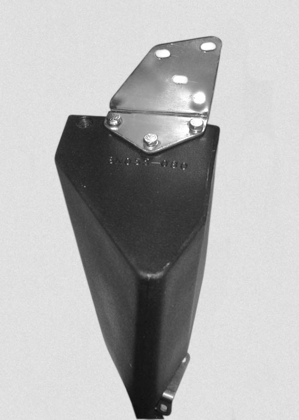
3. Attach bracket 4FU010-061 to the front of the reservoir with the hardware provided. (See Fig. 8C-b.)
Fig. 8C-b
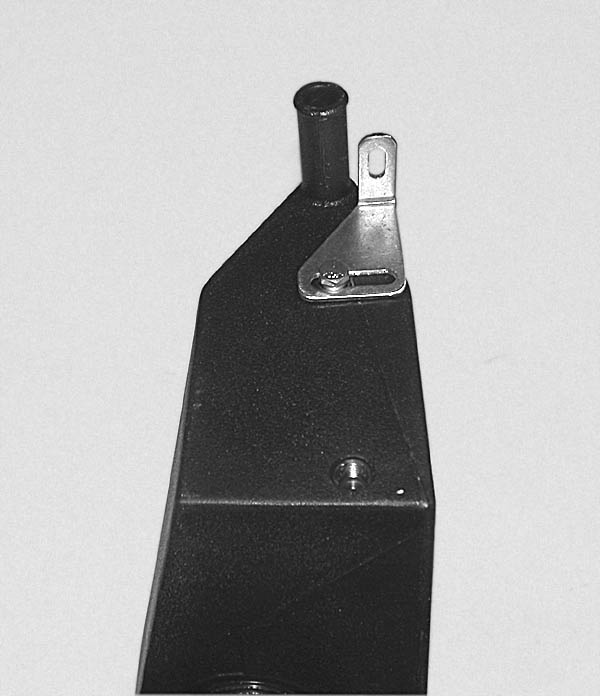
4. Locate and install 1/4"NPT x 3/8" barbed fitting in the tapped hole just above the previously installed mounting bracket. This hole may have to be opened using the appropriate drill bit. (See Fig. 8C-c.)
Fig. 8C-c
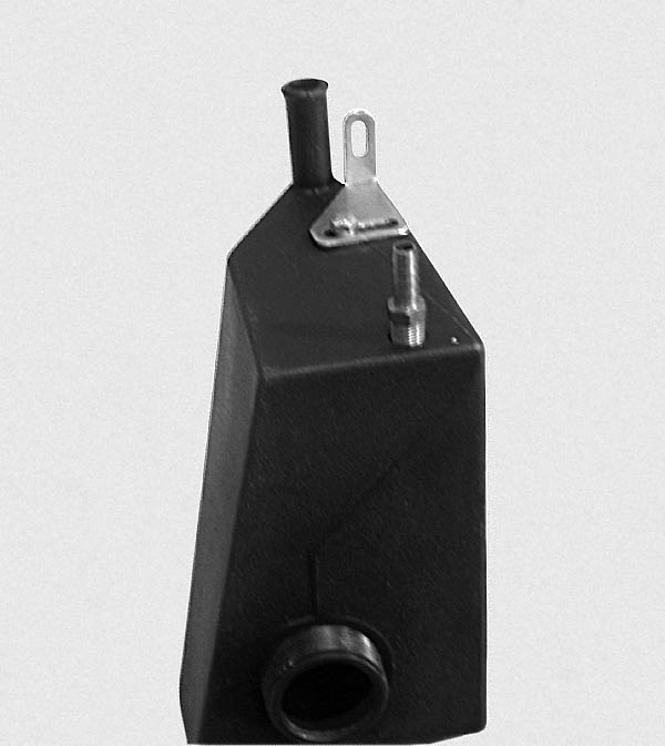
5. Remove the 10mm headed bolt that secures the back of the ECU and the power distribution box. (See Fig. 8C-d.)
Fig. 8C-d
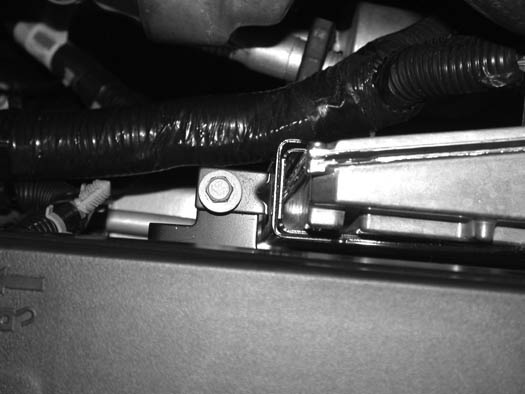
6. Install the coolant reservoir. Secure the front of the reservoir with the factory fastener removed previously. (See Fig. 8C-e.)
NOTE: Leave this bolt loose for final adjustment in a later step.
Fig. 8C-e
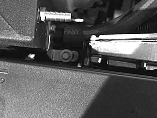
7. Attach the rear mounting bracket with the surge tank mounting bracket to the strut tower with the 6mm x 20mm long screws and washer provided. (See Fig. 8C-f.)
NOTE: Reinstall the factory ground wire with one of the 6mm screws and washers.
Fig. 8C-f
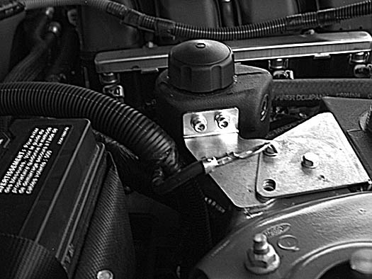
8. Attach a length of 3/4" hose (approximately 3' long) to the 3/4" bung on the front of the coolant reservoir. Route the hose to the 3/4" outlet on the thermostat housing secure the hose with the clamps provided. (See Fig. 8C-g.)
Fig. 8C-g
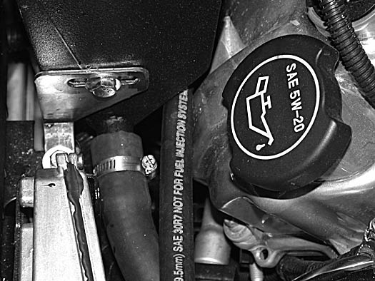
NOTE: A/C line on the passenger side must be bent away from block for reservoir clearance. This can be done with a large screwdriver as depicted in figure 8C-g2.
Fig. 8C-g2
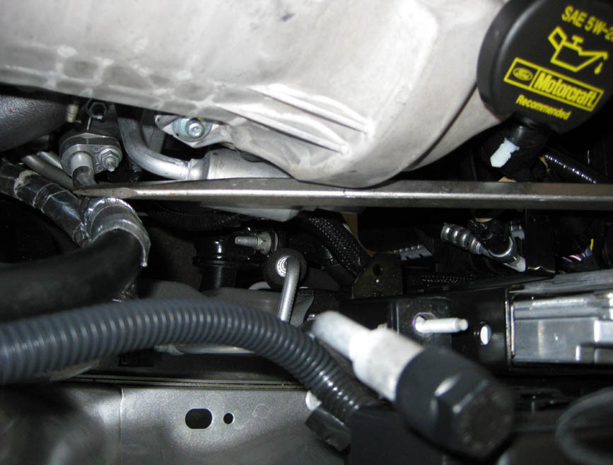
9. Modify the small hose removed from the factory coolant overflow reservoir. By cutting the "S” bend off the hose end. (See Fig. 8C-h.)
Fig. 8C-h
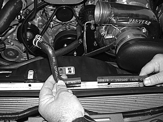
10. Install a 3/8" union and a #17 stepless clamp. Secure the clamp. Using a length of 3/8" (approximately 40" long) hose that is provided, secure the hose to the union with a #17 stepless clamp. (See Fig. 8C-i.)
Fig. 8C-i

11. Route the overflow hose across the radiator and under the radiator retaining bracket to the 1/4"NPT x 3/8" hose barb fitting in the coolant reservoir securing with a clamp. (See Fig. 8C-j.)
Fig. 8C-j

D. RADIATOR HOSE MODIFICATIONS ('05-'06 Models Only)
1. Remove the passenger’s side upper radiator hose. (See Fig. 8D-a.)
Fig. 8D-a
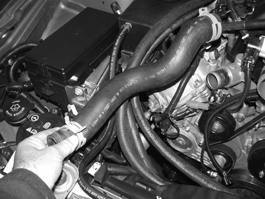
2. Modify the upper hose by cutting the hose just after the bend. (See Fig. 8D-b.)
Fig. 8D-b
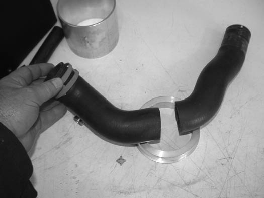
3. Attach the hose to the formed stainless tube 4FU014-010 with a #24 hose clamp.
4. A section of 1-1/2"ID hose left from the coolant tube relocation will be cut to approximately 2-3/4" long and attached to the outlet of the radiator reusing the factory spring clamp to secure the hose to the outlet.
5. Install the formed coolant tube to the inlet on the engine and to the radiator. Secure with hose clamps. (See Fig. 8D-c.)
Fig. 8D-c
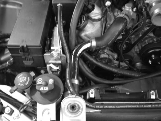
E. ENGINE COOLANT RESERVOIR INSTALLATION (2007-2010 Models Only)
1. Locate assembly 8N155-082.
2. Attach the rear reservoir mounting bracket 4FU010-091 to the reservoir with the 1/4-20 x 1/2" long bolts and washers provided. (See Fig. 8E-a.)
Fig. 8E-a
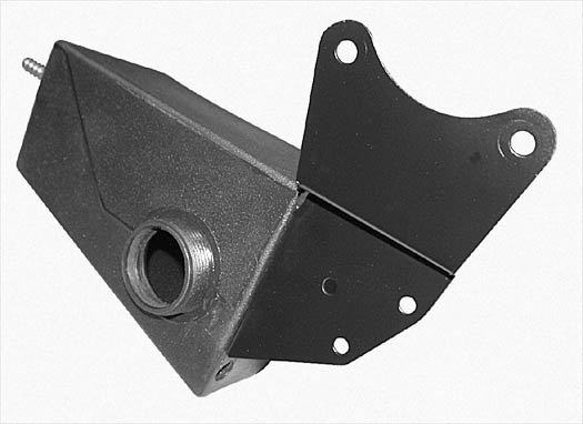
3. Attach bracket 4FU010-061 to the front of the reservoir with the hardware provided. (See Fig. 8E-b.)
Fig. 8E-b

4. Locate and install 1/4"NPT x 3/8" barbed fitting in the tapped hole just above the previously installed mounting bracket. This hole may have to be opened using the approppriate drill bit. (See Fig. 8E-c.)
Fig. 8E-c

5. Remove the 10mm headed bolt that secures the back of the ECU and the power distribution box. (See Fig. 8E-d.)
Fig. 8E-d

6. Install the coolant reservoir. Secure the front of the reservoir with the factory fastener removed previously. (See Fig. 8E-e.)
NOTE: Leave this bolt loose for final adjustment in a later step.
Fig. 8E-e

7.1 Attach the rear mounting bracket with the surge tank mounting bracket to the strut tower using the factory strut mounting hardware. (See Fig. 8E-f.)
Fig. 8E-f
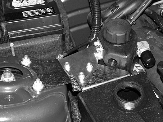
7.2 (Bullitt Only) Attach bracket 4FU010-061 on the underside of the 4FU010-091 reservoir bracket to ensure clearance from strut tower brace.
8. Attach a length of 3/4" hose (approximately 22" long) to the 3/4" bung on the front of the coolant reservoir. Secure using one of the #10 hose clamps provided. Route the open end of the hose to the 1" hose previously connected to the factory coolant reservoir. Connect and secure the two hoses using the 3/4" x 1" hose union, the factory 1" spring clamp and the #10 hose clamp provided.
Fig. 8E-g

9. Modify the small hose removed from the factory coolant overflow reservoir. By cutting the "S” bend off the hose end. (See Fig. 8E-h.)
Fig. 8E-h

10. Install a 3/8" union and a #17 stepless clamp. Secure the clamp. Using a length of 3/8" (approximately 40" long) hose that is provided, secure the hose to the union with a #17 stepless clamp. (See Fig. 8E-i.)
Fig. 8E-i
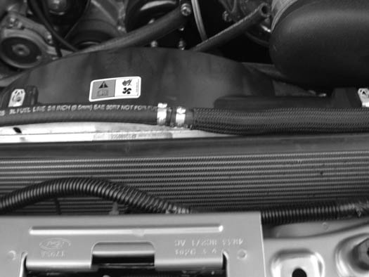
11. Route the overflow hose across the radiator and under the radiator retaining bracket to the 1/4"NPT x 3/8" hose barb fitting in the coolant reservoir securing with a clamp. (See Fig. 8E-j.)
Fig. 8E-j

F. COOLER CORE INSTALLATION
1. Locate the charge air cooler assembly.
2. Attach the 4.5" x 2" sleeve to the throttle body and secure with a #72 hose clamp.
3.a (Non-V-Power/Bullitt Kits only) Install the 1/2"NPT x 3/4" barb 90° and straight fittings into the charge cooler as shown. (See Fig. 8F-a.)
Fig. 8F-a
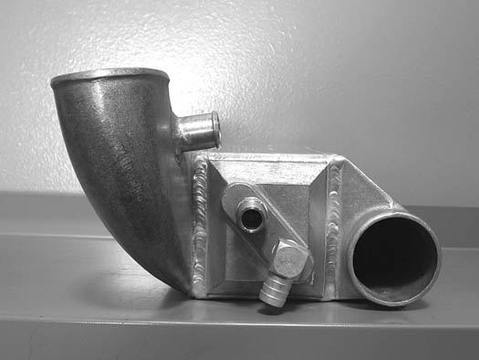
3.b (V-Power/Bullitt Kits only) Install the two 1/2" NPT x 3/4" barb 90º fittings into the charge cooler as shown (See Fig. 8F-b)
Fig. 8F-b
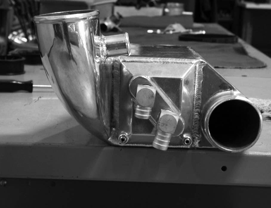
4. Attach the long end of the 2.75" (3" if V-Power) silicone elbow to the cooler inlet and loosely install a #44 (#48 on V-Power cars) hose clamp. The open end of the elbow should be facing up as it will be attached to the supercharger discharge.
5. Lower the cooler assembly into position. Attach the open end of the previously installed 2.75" elbow to the supercharger discharge and loosely install a #44 hose clamp.
6. Attach the cooler discharge to the previously installed sleeve on the throttle body. Secure with a #72 hose clamp.
7. Tighten all cooler clamps at this time.
8. Locate one of the remaining 3/4" molded 90°. Trim approximately 5" from the long end and attach the short end to the forward most 3/4" x 90° fitting previously installed in the cooler. Secure with the nylon ratchet clamp provided.
9. Install a 3/4" hose union into the open end of the previously installed hose. Attach a section of 3/4" hose approximately 32" long to the union. Route the open end of the hose to the surge tank. Using the remaining adel clamp and factory hardware, secure the hose to the factory coolant reservoir mounting location. (See Figs. 8B-q, 8F-c for assistance.) Secure all hose connections with the supplied nylon ratchet clamps.
Fig. 8F-c
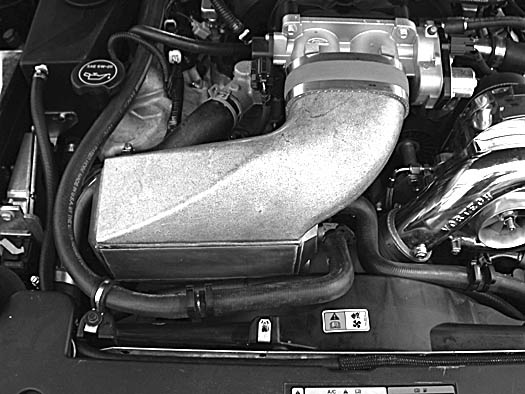
10a. (Non-V-Power/Bullitt Kits only) Locate the supplied “S” shaped hose. Trim approximately 1" from the short end and attach it to the straight fitting previously installed in the cooler. Install a 3/4" hose union into the open end of the “S” hose. Attach a section of 3/4" hose approximately 24" long to the union and route to the driver’s side and down to the water cooler. Trim for best fit and connect to the 3/4" hose union previously installed in the 90° short rubber hose attached to the top water port on the CAC cooler.
NOTE: The installation of this hose section should maintain an “uphill” routing without dips or kinks.
10b (V-Power/Bullitt Kits only) Locate the remaining 3/4" molded 90° hose and install on the rear most 3/4" x 90° fitting previously installed in the CAC. Secure with the nylon ratchet clamp provided. Trim as required. Using the supplied 3/4" barb union connect the other end of the molded 90° hose to a section of 3/4" hose approximately 24" long routed to the driver side and down to the top of the water cooler. trim for best fit and connect to the 3/4" hose union previously installed in the 90° short rubber hose attached to the top port on the CAC water cooler.
11. At this time, verify that all hose connections are secure using the nylon ratchet clamps provided.
12. (2007-2010 Models Only) To provide additional clearance for the CAC, you will need to cut the factory radiator hose approximately 4" from its connection at the radiator. Install the supplied Ø1.5" x 4" hose union and two #24 hose clamps. Adjust to allow CAC clearance and secure. (See Fig. 8F-c.)
Fig. 8F-c (2007-10 MODELS ONLY)
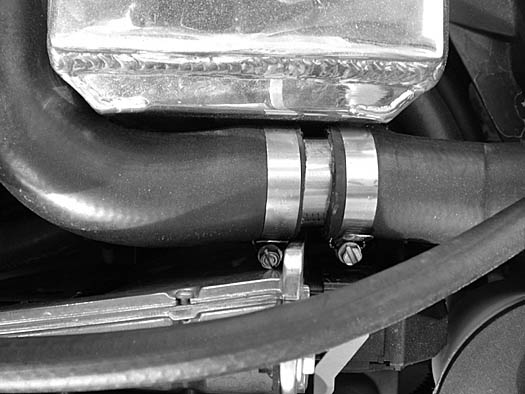
G. COOLANT RESERVOIR FILL
1. Check to make sure all previously installed hose connections are secure.
2. Fill the engine cooling system through the Vortech supplied coolant reservoir using the factory coolant previously drained.
3. Locate the factory coolant reservoir cap removed in section 1 and install it on the Vortech supplied reservoir.
4. (2005-2006 Only) Once the coolant system is filled and all trapped air expelled, install the 1/8"NPT plug provided in the previoisly installed cross-over tube. Thread sealant should be used.
5. CAC cooling system.
a. Temporarily remove the 3/4" hose attached to the 3/4" x 90° fitting on the CAC surge tank.
b. Cap the open end of the 3/4" x 90° fitting using the provided vinyl cap.
c. Fill the CAC system using a 25%/75% antifreeze/water mix. Using a funnel, fill through the 3/4" hose removed from the surge tank fitting.
d. Fill the system until the coolant level reaches the surge tank.
e. Remove the vinyl cap from the surge tank fitting and reinstall the 3/4" hose previously removed and secure with the nylon ratchet clamp.
6. Reinstall the front bumper assembly including the foam inner bumper, all plastic splash panels and light connections in the reverse order removed.2010 Models skip this step and see section 8H.
H. BUMPER COVER MODIFICATION (2010 MODELS ONLY)
1. 2010 Models will require the removal of the lower grill uprights and certain surronding areas to clear the water cooler. (See Fig. 8H-a)
Fig. 8H-a
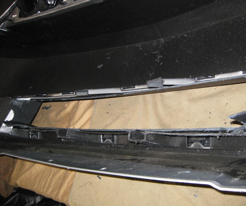
2. Cut out vertical supports in lower grill opening. the upper lip of the grill should be trimmed back to approximately 4-1/4” when measured from the back side of the grill. (See Fig. 8H-b)
Fig. 8H-b
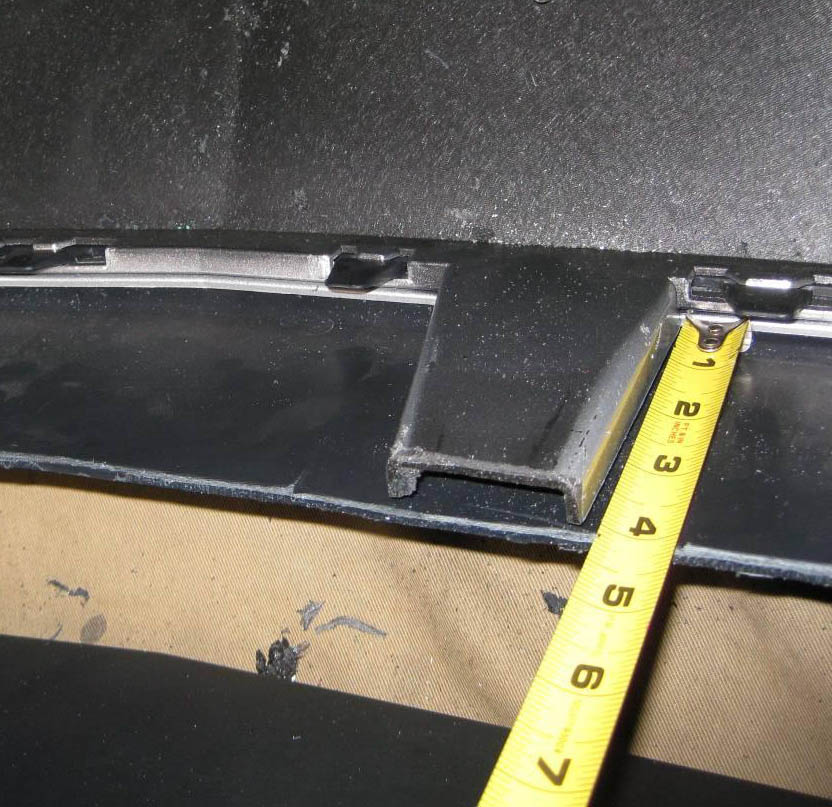
3. The lower lip should be trimmed back approxi mately 4-1/4” measured from the front of the grill. (See Fig. 8H-c)
Fig. 8H-c
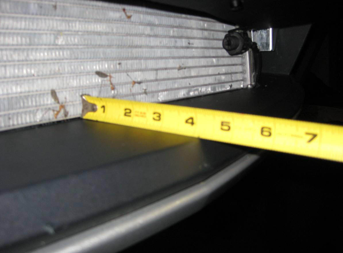
4.. Trial fit bumper and check for interference against intercooler. Additional removal of mate rial may be required to clear the intercooler end tanks and brackets (See Fig 8H-d,e).
Fig. 8H-d
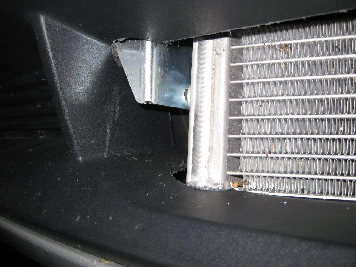
5. Remove bumper and mark on upper lip supports 1” from edge. Drill a 1/4 “ hole from the top of the support through the lip of the grill. From the bottom drill a 5/16” hole through the lip only, being careful not to drill through the support. An angle drill using the shortest bit possible is recommended.
Fig. 8H-e
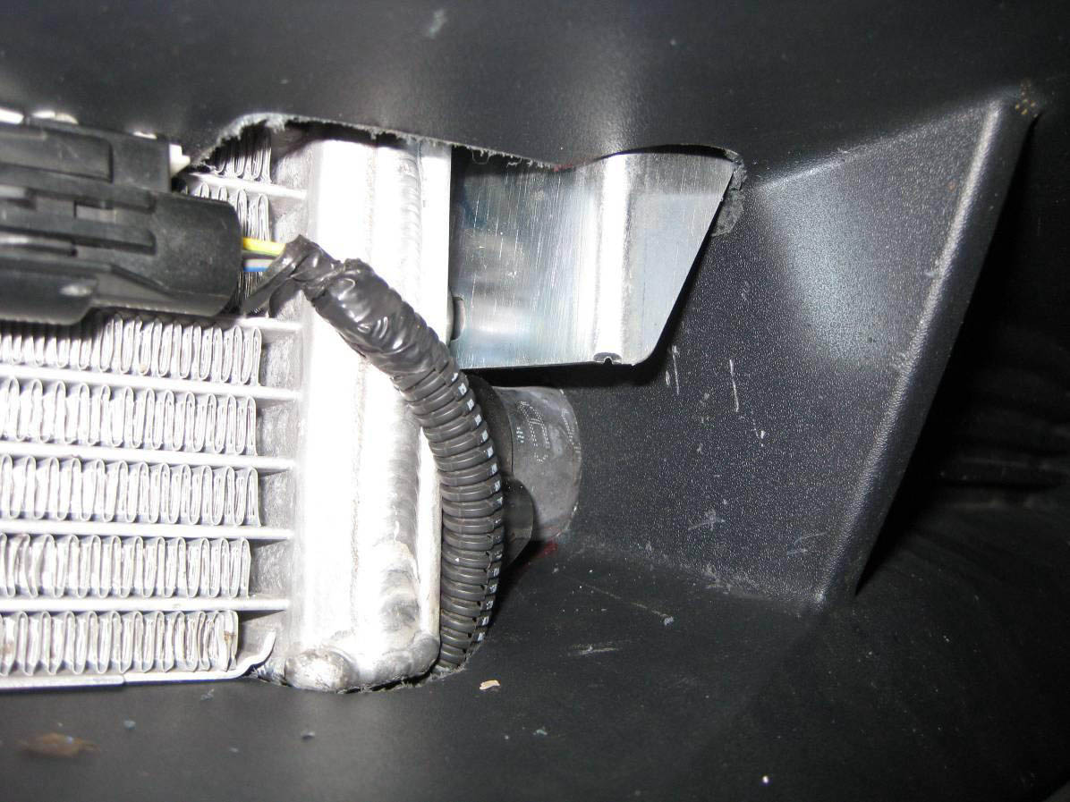
5. Install the supplied 1/4-20 Nylon shouldered bolts from the lip side so that the threads pro trude through the supports and attach with the supplied 1-4/20 Nylock nut (See Fig. 8H-f). Do not over tighten nuts.
Fig. 8H-f
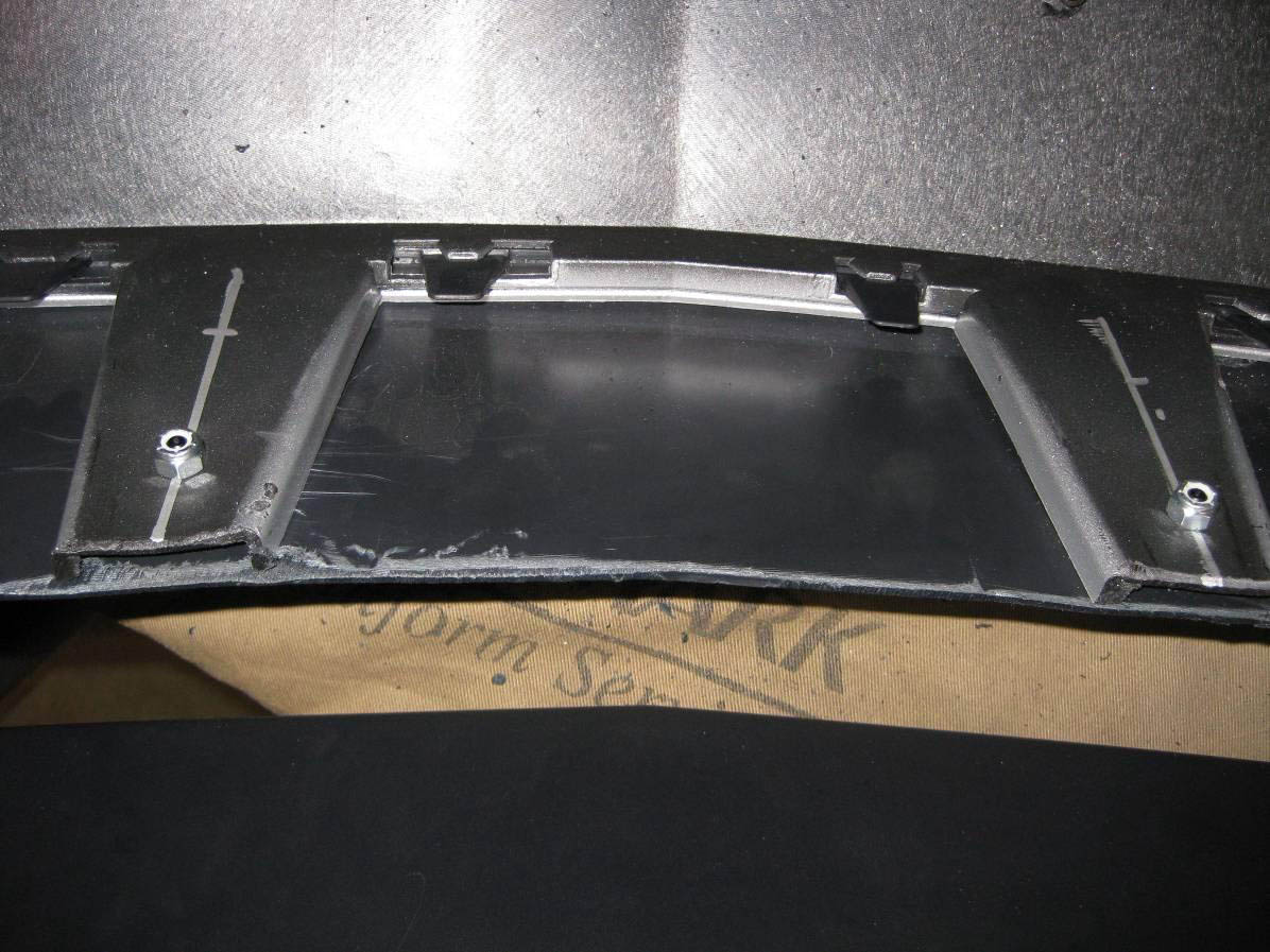
6. Reinstall the front bumper assembly including the foam inner bumper, all plastic splash panels and light connections in the reverse order removed. See Fig. 8H-g for final installation reference
Fig. 8H-g
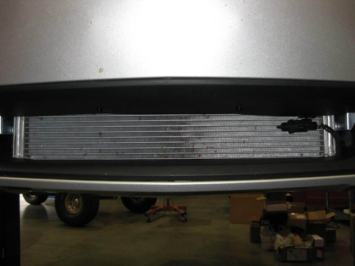
I. COMPRESSOR BYPASS VALVE INSTALLATION (V-POWER/BULLIT KITS SKIP TO 8J)
1. Assemble the bypass using a piece of 1" hose cut to 11" long and a piece cut to 13" long and four #16 hose clamps.
2. Attach the 11" piece of hose to the inlet of the bypass and secure with a clamp.
3. Secure the 13" piece to the outlet of the valve, securing it with a clamp. (See Fig. 8I.)
Fig. 8I
4. Attach the bypass assembly to the charge cooler. The 11" long piece will be attached to the charge cooler. Secure with clamps. Leave the 13" long section open for future attachement to the air inlet.
5. Attach a length of 5/32" vacuum hose to the bypass valve and route to the vacuum port of the fuel rail sensor.
6. Cut a section of the factory hose and install the vacuum TEE that is provided. (See Fig. 10-b)
7. Attach the vacuum hose from the bypass valve to the TEE.
J. V-POWER/BULLIT COMPRESSOR BYPASS VALVE INSTALLATION
1. Assemble the bypass using the supplied Maxflow Race Bypass valve, Ø 1.75" silicone coupler with two #28 hose clamps, Bypass "Y", and two lengths of 1" hose cut to lengths of 16" and 17.5" with four #16 hose clamps. (See Fig. 8J)
Fig. 8J
2. Attach the Maxflow Race Bypass Valve to the flange located on the lower duct of the CAC using the supplied hardware and gasket.
3. Attach one end of the Ø 1.75" silicone coupler to the outlet of the bypass valve and secure with #28 hose clamp.
4. Insert the Ø 1.75" side of the bypass "Y" into the open end of the Ø 1.75" silicone coupler and secure with #28 hose clamp.
5. Secure the two lengths of 1" hose cut to 16" and 17.5" to the two outlets on the bypass "Y" with #16 hose clamps (See Figure 8I-a for orientation).
6. Leave the opposite ends of the 1" hose open for future attachment to the air inlet box.
7. Attach a length of 5/32" vacuum hose to the bypass valve and route to the vacuum port of the fuel rail sensor.
8. Cut a section of the factory hose and install the vacuum TEE that is provided (See Fig. 10-b).
9. Attach the vacuum hose from the bypass valve to the TEE
9. AIR DISCHARGE ASSEMBLY (Non-cooled kits only)
A. Attach the 4.5" sleeve to the discharge duct with the #72 clamps provided.
B. Install the 3.0" x 2.75" reducer to the inlet of the discharge duct and secure the #48 hose clamp provided.
C. Install the duct to the inlet of the throttle body and the outlet of the supercharger Secure the remaining #72, and #44 hose clamps provided. (See Fig. 9-a.)
Fig. 9-a
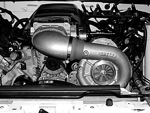
10. COMPRESSOR BY-PASS VALVE INSTALLATION (Non-cooled kits only)
A. Assemble the compressor by-pass valve by using a piece of 1" hose cut 15" long and a piece cut to 4.25" long, and four #16 hose clamps.
B. Attach the 4.25" piece of hose to the inlet of the bypass and secure with a #16 clamp.
C. Secure the 15" piece to the by-pass valve outlet using a #16 hose clamp. (See Fig. 10-a.)
Fig. 10-a
D. Attach the open end of the 4.25" hose to the boss on the air discharge duct. Secure with a #16 hose clamp. The open end of the 15" long hose will be connected to the air inlet in a future step.
E. Secure all hoses with the clamps provided.
F. Connect the supplied length of 5/32" vacuum to the port on the bypass valve. Route the line to the fuel regulator vacuum hose. Using the supplied vacuum TEE, connect the bypass vacuum line. (See Figs. 10-a, 10-b, for assistance.)
Fig. 10-b
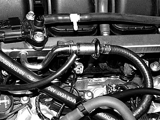
11. COOLANT RESERVOIR RE-INSTALLATION (Non-cooled kits only)
A. Reinstall the factory coolant reservoir using factory hardware to secure.
B. Reattach the large hose at the bottom of the reservoir using the factory hose clamp.
C. Reconnect the small overflow hose at the top using the factory clamps.
D. Check all cooling system hose connections to make sure they are secured with the appropriate hose clamps.
E. Refill the cooling system using the previously drained coolant.
F. (2005-2006 Only) Once the coolant system is filled and all trapped air expelled, install the 1/8"NPT plug provided in the previously installed crossover tube. Thread sealant should be used.
12. CRANK CASE BREATHER AND PCV INSTALLATION
A. Locate PVC/MAF assembly 4FU139-096.
B. Install the hose assembly between the driver’s side valve cover and the intake manifold. Secure hose connections as necessary using the supplied stepless clamps.(See Figs. 12-a, 12-b for assistance.)
Fig. 12-a
Fig. 12-b
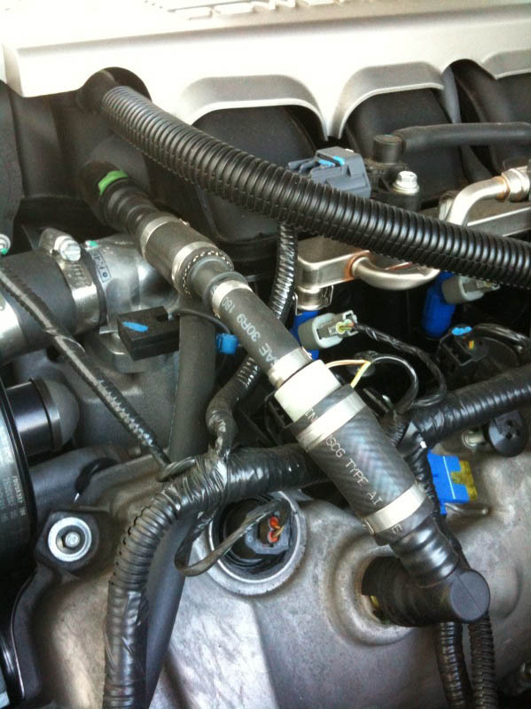
C. Locate the factory 3/8" x 90° fitting removed from the passenger’s side valve cover in a previous step.
D. Connect the remainder of the supplied 3/8"ID hose to the 90° fitting and connect to the passenger’s side valve cover. (See Fig. 12-c.)
Fig. 12-c
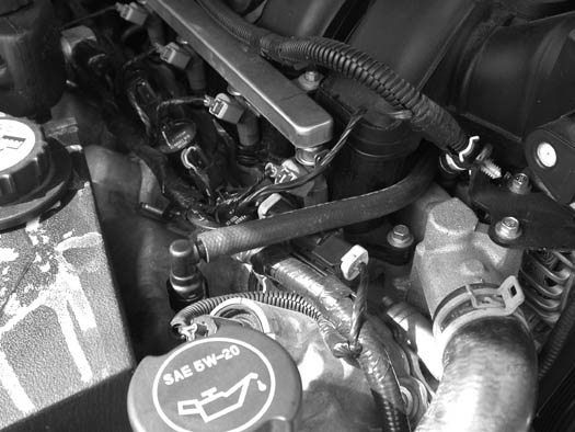
E. Route the open end of the 3/8" hose behind the alternator and across to where the air inlet duct will be located.
13. AIR INLET ASSEMBLY
A. Locate assembly 4FU112-010.
B. Remove two of the 3/8-16 x 1" bolts securing the supercharger in place. Install the air inlet support bracket and secure with the 3/8" bolts removed from the supercharger mounting plate. (See Fig. 13-a.)
Fig. 13-a
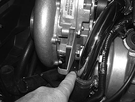
C. Install the 3/4"NPT x 1" x 90° plastic fitting to the air inlet duct. (See Fig. 13-b.)
Fig. 13-b
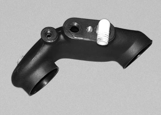
D. Install the 1/4"NPT x 3/8" hose barb fitting in the location noted. (See Fig. 13-c.)
Fig. 13-c
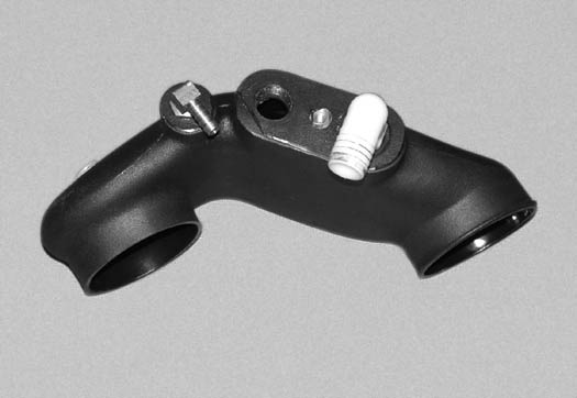
D.2 (V-Power/Bullitt Kits Only) Drill out the second 3/4" NPT location on the air inlet duct using caution not to damage the threads and install the second 3/4" NPT x 1 x 90° plastic fitting to the air inlet duct. Orient both fittings as shown in Fig 13-d2.
E. Attach the 4.0" x 3.5" reducer sleeve to the inlet duct. Secure the sleeves with the clamps provided. (See Fig. 13-d.)
Fig. 13-d
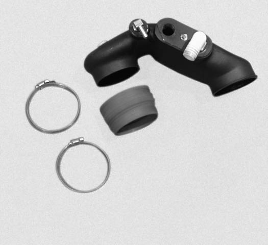
Fig. 13-d2 (V-Power/Bullitt Kits Only)
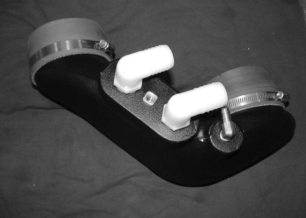
F. Attach the 3/8" hose previously connected to the passenger’s side valve cover, to the 1/4"NPT x 3/8" hose x 90° fitting installed in a previous step.
G. Attach the 1" bypass outlet hose to the 90° plastic fitting and secure the hose with a #16 hose clamp.
H. Install the duct to the inlet of the supercharger and secure in place with the clamps provided.
I. Locate and install a 4.0" x 2.0" long sleeve to the inlet of duct 4FU012-010 and secure with two #64 clamps. (See Fig. 13-e.)
Fig. 13-e
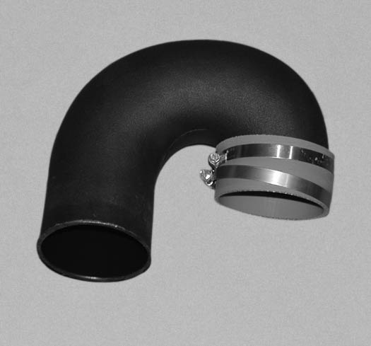
J. Remove the Factory MAF sensor element from the top portion of the air filter housing.
K. Install the element using the 4mm hardware provided to the supplied MAF tube. (See Figs. 13-f, 13-g.)
Fig. 13-f
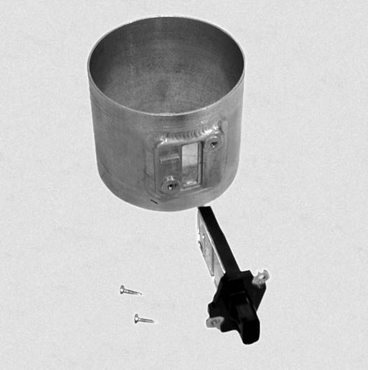
NOTE: Install the MAF sensor element so the inlet of the sensor faces the air filter. (See Fig. 10-h.)
Fig. 13-g
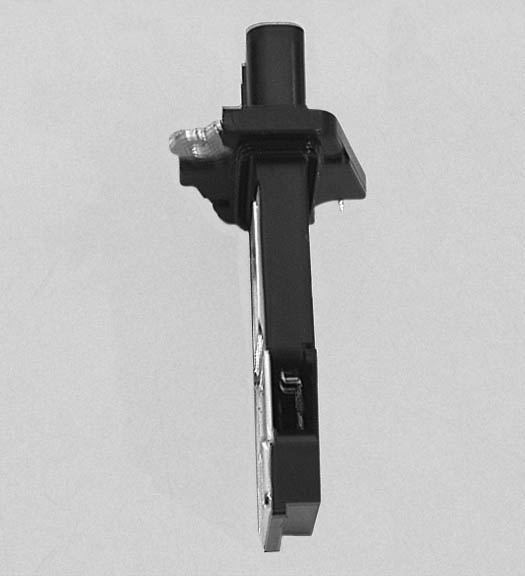
L. Install the MAF sensor and air filter to the 180° duct. (See Fig. 13-h.)
Fig. 13-h
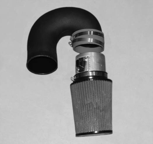
M. Install the 180° duct and the MAF sensor with filter to the inlet duct leading to the Supercharger. (See Fig. 13-i.) Clock the MAF exactly as shown. (See Fig. 13-i.)
Fig. 13-i
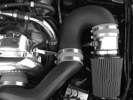
N. Secure the rear clamp at the inlet duct union to the previously installed support bracket. (See Fig. 13-i.)
O. MAF (Mass Air Meter) (Non-Cooled Kits Only) Harness Extension:
1. Locate the supplied wire and butt connectors in assembly 4FU101-001.
NOTE: It is strongly recommended that the wires be soldered. Temporary solderless connectors have been provided in case you are unable to solder.
2. Remove the split loom from the factory wires on the MAF sensor.
3. Cut the wires to the connector approximately 2" from the plug.
4. Using the supplied connectors and wire, extend the connector to the MAF.
5. Install the supplied 3/8" split-loom to the extended sensor plug harness. Secure the split-loom with wire-ties or tape.
6. Route the lengthened wires and connector to the MAF, keeping the wires away from hot or moving parts.
P. MAF Interface Adapter Installation (Charge Cooled kits only)
1. Locate the MAFia (Interface Adapter) box.
2. Plug the MAFia in between the factory MAF connector and the MAF sensor.
3. Remove the small red cover in the middle of the supplied MAFia box.
4. Verify that the MAFia box is set on number “2”.
5. If you find that the MAFia box is not set, use the tool that is provided with the MAF Interface Adapter box and set to the number “2”.
6. Replace the cover and secure the MAFia box and set to the number “2”.
NOTE: It is critical that the MAF Interface Adapter box be set on number “2”, The calibration that is provided with this kit has been created to work at this setting. Any change to the MAF Interface Adapter box by setting it to a higher or lower number could cause damage to the engine.
Q. On 2010 models it will be neccesary to bend the hood latch cable bracket 90° for air filter clearence.(See Fig 13-j)
Fig. 13-j
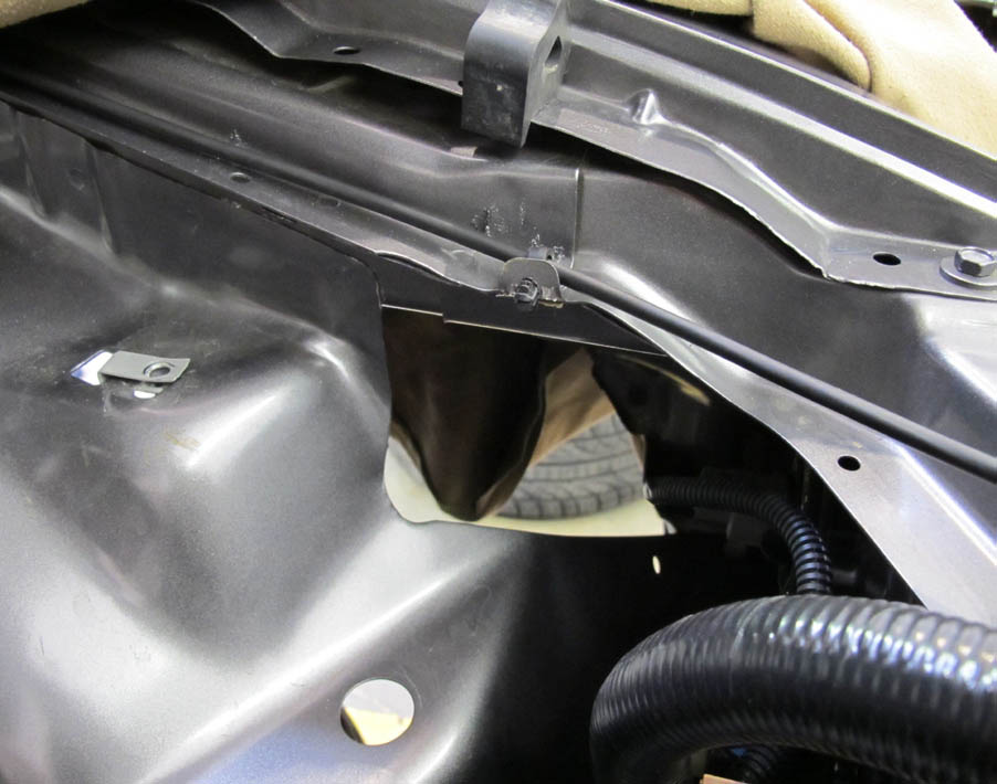
14. FUEL PUMP UPGRADE
NOTE: This section is best performed with the fuel level BELOW half a tank.
A. Remove the rear seat by depressing the two release buttons at the front edge of the seat. (See Fig. 14-a.)
Fig. 14-a
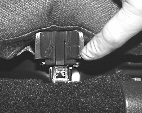
B. Remove the round plastic inspection cover on the driver’s side. (See Fig.14-b.)
Fig.14-b
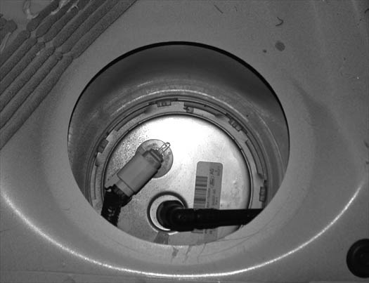
C. Unplug the sending unit harness and disconnect the fuel line connection.
D. Using a small screwdriver or chisel and hammer, tap the retaining ring in a counter clockwise direction. Remove the retaining ring and set aside. (See Fig. 14-b.)
E. Slowly pull the fuel pump assembly up. Locate the crossover fuel line connection on the fuel pump assembly and disconnect. (See Fig. 14-c.)
Fig. 14-c
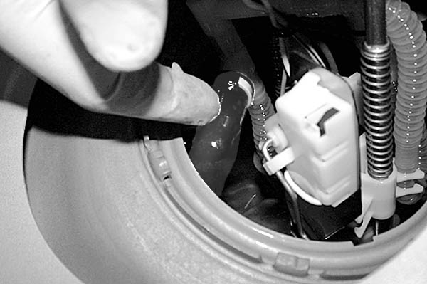
F. Remove the pump assembly from the tank being careful not to damage or lose the rubber O-ring.
G. Carefully cut the step-less clamps securing the short corrugated fuel line between the fuel pump outlet and distribution rail. Remove the fuel line and discard. (See Fig. 14-d.)
Fig. 14-d
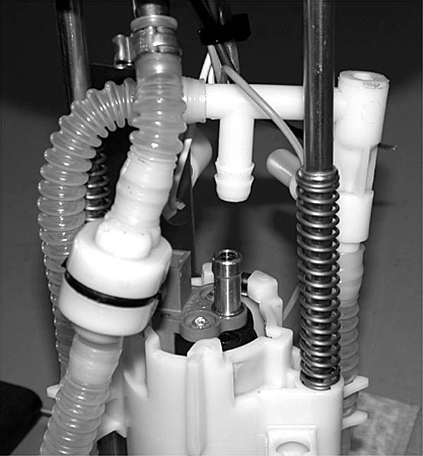
H. Using the supplied 17.0 stepless clamps and 2.75" length of Ø3/8" rubber hose, connect the supplied “Y” fitting to the distribution rail. (See Fig. 14-e.)
Fig. 14-e
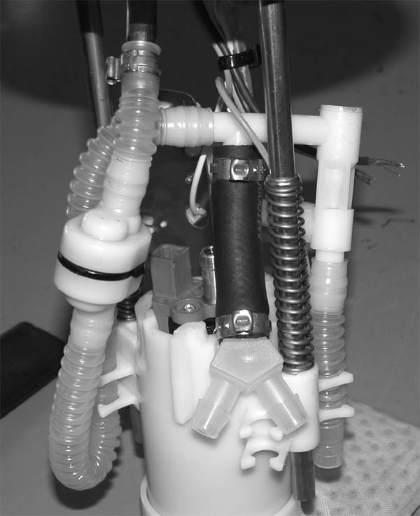
I. Locate the supplied fuel pump and pump inlet screen. Attach the pump inlet screen to the pump and orient exactly as shown. (See Fig. 14-f.)
Fig. 14-f
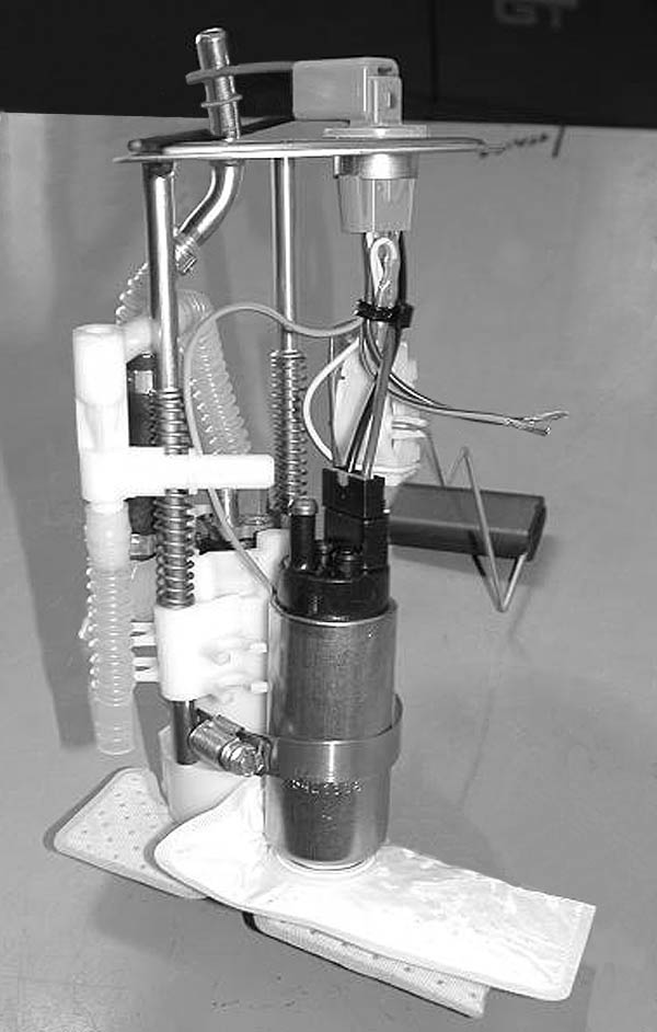
J. Secure the supplied fuel pump to the side of the factory pump assembly using the #44 hose clamp supplied. Verify that the hose clamp is routed inside of the metal posts so that they can be pushed down without restriction. (See Fig. 14-f.)
K. Slide the two supplied .75" long teflon sleeves over the discharge of each fuel pump. (See Fig. 14-g.)
NOTE: The supplied 1.5" long Teflon tube will need to be cut into two .75" long pieces.
Fig. 14-g
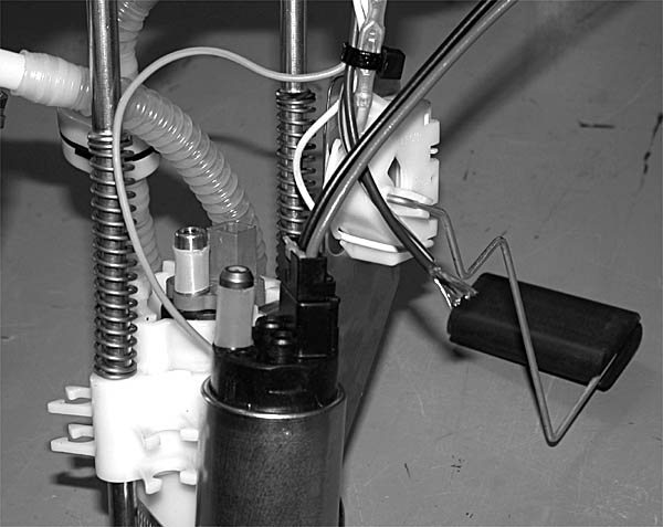
L. Slide the supplied 11.3 stepless clamps onto the two open legs of the Y-fitting. Connect the discharge of both pumps to the previously installed “Y” fitting using the two supplied Ø3/8" corrugated teflon hoses. Secure the remaining hose ends using the supplied 11.3 stepless clamps. (See Fig. 14-h.)
M. Secure all hoses to the fuel pump assembly using the supplied ties. Make sure the lid is able to spring up and down without restriction and that the hoses do not kink. (See Fig. 14-h.)
N. Use the supplied T-splice and slide connectors to connect the black and red wires from the supplied pump to the corresponding power and ground on the factory pump. (See Fig. 14-h.)
Fig. 14-h
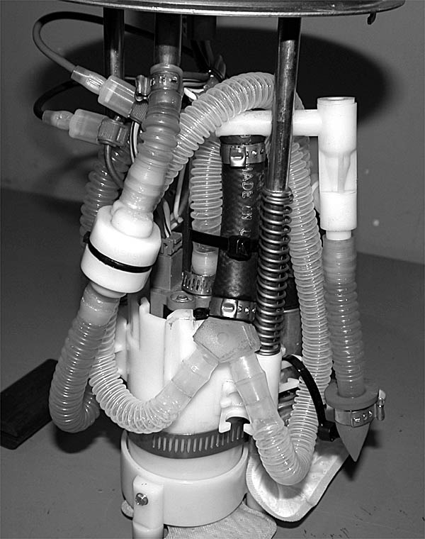
O. Reinstall the fuel pump assembly into the fuel tank in the reverse order of removal. Ensure that the fuel hoses do not rub on the sharp edges of the fuel tank. Take care not to damage the assembly. INSTALLATION WILL BE TIGHT. Connect all fuel and electrical connections. Verify that the fuel gauge float is able to move freely. Make sure the O-ring seal is in place and not damaged. There is an alignment arrow on the pump assembly top that will need to be aligned with the dot on the fuel tank. (See Fig. 14-b.)
NOTE: Retaining ring indents must engage their receivers for proper seal. (See Fig. 14-b.)
P. Locate the power distribution box located on the passenger’s side of the engine compartment. Verify the #41 fuse is for the fuel pump.(2010 Model year uses #13) Replace the factory 15AMP fuse with the supplied 20AMP fuse.
Q. Cycle the ignition key and check for any fuel leaks, verify proper fuel gauge operation.
R. Reinstall the plastic inspection cover and rear seat.
15. REFLASH COMPUTER
IMPORTANT! To ensure trouble-free programming of your vehicle's computer:
• Make sure the vehicle's battery is sufficiently charged.
• Turn off all accessories and close doors to prevent unnecessary drain on the battery.
• Do not attempt to program your vehicle while a battery charger is connected.
• Improper battery voltage will result in failure of the programming process.
• Do not disconnect the cable or turn off the ignition during programming.
A. Reconnect the battery.
B. Locate the vehicle’s OBD2 connector located in the lower left hand corner of the dash on the driver’s side of the vehicle. (See Fig 15-a.)
Fig 15-a
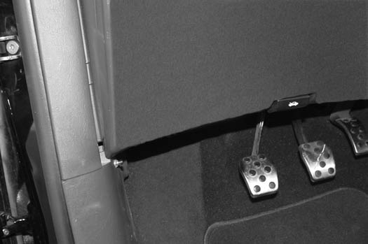
C. Attach the OBD2 connector from the Flash tool (provided in the kit) to the vehicle’s OBD2 port. (See Fig 15-b.) Make sure this connector is seated all the way into the vehicle’s OBD2 port. You do not want this connector coming out during programming or damage may occur to the vehicle’s ECM.
Fig 15-b
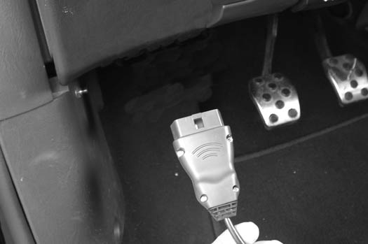
D. The Reflash tool should power up and display three parameters:
1. Performance Tune
2. Diagnostics
3. Options
E. Select “Performance Tune” and press the enter button in the middle of the arrow keys. (See Fig 15-c.)
Fig 15-c
F. Read the disclaimer entirely, then select agree and press enter.
G. At this point please read the screen displayed on the reflash tool. If you have any questions, either refer to the manual provided with the reflash tool or contact our service department for further assistance.
H. Turn the ignition on (do not start the vehicle). Set the parking brake and press the “enter” button to continue.
I. “SELECT TUNE” will be displayed at the top of the screen. Use the arrow keys to select the appropriate tune for your vehicle and press the enterbutton. You will have four choices to select from:
1. STD OUTPUT (non charge-cooled)
2. Charge-cooled, air/water
3. Charge-cooled, air/air (this option is NOT used in this application)
4. Original Backup
J. Continue to follow the screen and when finished unplug the reflash tool from the vehicles OBD2 port.
NOTE: Do not disturb the cable, or turn the ignition off during this time. If the programming is disrupted, the computer will not start or run your vehicle!
16. FINAL CHECK
WARNING: Do not attempt to operate the vehicle until all components are installed and all operations are completed including the final check.
A. If your vehicle has gone over 15,000 miles since its last spark plug change, you will need to change the spark plugs now before test driving the vehicle.
B. Check all fittings, nuts, bolts and clamps for tightness. Pay particular attention to oil and fuel lines around moving parts, sharp edges and exhaust system parts. Make sure all wires and lines are properly secured with clamps or tie-wraps.
C. Check all fluid levels, making sure that your tank(s) is/are filled with 91 octane or higher fuel before commencing test drive.
D. Start the engine and allow to idle a few minutes, then shut off.
H.O Charge Cooled Kits Only Note: Check to see that CAC coolant is flowing through the surge tank. If coolant is not flowing, remove the 3/4" rubber hose from the side of the surge tank and apply light suction in an attempt to pass any trapped air in the system. Reconnect the hose and recheck coolant flow.
E. Recheck to be sure that no hoses, wires, etc. are near exhaust headers or moving parts. Look also for any signs of fluid leakage.
F. PLEASE TAKE SPECIAL NOTE: Operating the vehicle without ALL the subassemblies completely and properly installed may cause FAILURE OF MAJOR COMPONENTS.
G. Test drive the vehicle.
H. Always listen carefully for engine detonation. Discontinue heavy throttle usage if detonation is heard.
I. Read the Street Supercharger System Owner's Manual and RETURN THE Warranty REGISTRATION FORM within thirty (30) days of purchasing your supercharger system to qualify.
For internally lubricated V3 units only
This supercharger has been factory pre-filled with special Vortech synthetic lubricant. Oil does not need to be added to a brand new unit; however a fluid level check should be performed.
Prior to operating the supercharger on the vehicle and after installation onto the vehicle:
Remove the factory installed flat-head brass shipping plug (not the dipstick) from the top of the supercharger case. Replace the sealed shipping plug with the supplied “vented” plug. Do not operate the supercharger without it. Check the supercharger fluid level.
Fluid level checking procedure:
1. Ensure that the .06” copper sealing washer is located on the dipstick base.
2. Thread the clean dipstick into the unit until it seats.
3. Once the dipstick has seated, remove the dipstick from the unit. Fluid should register in the crosshatched area on the dipstick.
4. DO NOT OVERFILL!!! Drain excess fluid from the unit if it is above the maximum level on the dipstick.
Check the fluid level using the dipstick at least every 2,500 miles.
Initial supercharger fluid change must be performed at 2,500 miles. The supercharger fluid must be changed at least every 7,500 miles.
Drain the fluid, refill the unit with 4 oz. of Vortech V3 lubricating fluid and then confirm proper oil level using the dipstick. DO NOT OVERFILL!!!
WARNING: Use of any other fluid other than the special Vortech lubricant will void the warranty and may cause component failure.
VORTECH Engineering, LLC
1650 Pacific Avenue, Channel Islands CA 93033-9901 • Phone: 805 247-0226Fax: 805 247-0669 • www.vortechsuperchargers.com • M-F 8:00AM - 4:30PM (PST)
